Explanation of the
Physical Lorentz Contraction and Time Dilation
based on Schrodinger’s Physical
Model of the Electron
Doug Marett, April, 2022
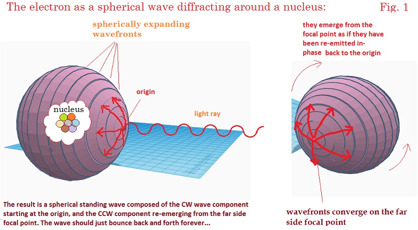
In Schrodinger’s
visual model of the electron first put forward in 1926, and again described in
his 1933 Nobel Prize address, the electron was conceived of as a “diffraction
halo” around the nucleus. In this model, the EM waves become trapped into a spherical
path by diffraction and the wavefronts oscillate between the two polar ends of
this sphere, forming an EM shell. This model was addressed in detail in our
previous paper. 1 and can be summarized in the diagram
shown below.
I would like to describe
herein how this model of the electron, or particles in general, should contract
in their direction of motion consistent with a physical interpretation of the
Lorentz contraction. We would also expect a dilation of oscillation period of spherical
standing wave. This assumes the electron is moving with respect to the frame of
reference in which the EM energy waves, i.e. a preferred frame for the speed of
light as called for In Lorentz’s theory or corresponding states.3
In Schrodinger’s
1933 model, the electron comprises a spherical standing wave, where the waves
travel in the forward and reverse directions between the poles of the sphere.
The wavelength of these waves is on the order of the circumference of the
sphere, and an integer or half-integer number of waves must fit the
circumference for the electron to be stable. We assume that the standing waves
are moving at the speed of light C in some medium in which the structure is at
rest, which is our preferred frame for the speed of light of these waves, and
would have an average wavelength l=C/f. If the electron
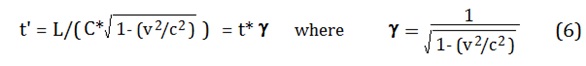
then moves at some velocity v from left to right, we would expect that from the
perspective of an observer moving with the electron, the propagation time t’ of the component of the spherical wave
moving in the forward direction over a distance L will become longer with
respect to its stationary state by the amount:

and the wavelength is then shorter by :

Conversely, the component of the wave moving in the reverse
direction will have its propagation time shortened by:

and
the wavelength is then longer by:

Thereby the average wavelength l’’’ of the standing wave across this segment is the
average of the two wavelengths above:
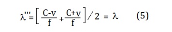
So
the average wavelength remains unchanged in the forward/reverse direction.
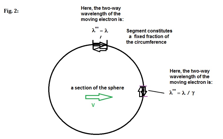
However, for the condition where the EM rays are propagating perpendicular to
the velocity v, the propagation time in both directions will be:
so
the average speed of light will be:
C’ = C/ g (7)
And
the average wavelength on the perpendicular segment will be shorter:
l’’’ = l / g (8)
For any intermediate segments between the parallel and
perpendicular segments, the average two-way wavelength will be shorter,
somewhere between l
and l/g.
To calculate these intermediate values in an angle-dependent
way, we first calculate the one-way wavelength on the segment using the
equation below: 4
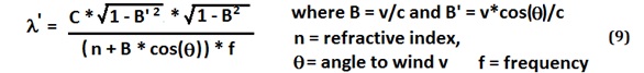
And
then use the forward and reverse wavelength at angle q and
angle q +180 degrees to calculate the average
wavelength l’’’ for the segment.
To
determine how the sphere would change shape with velocity, we then plot a 2D section
of the sphere in Excel as a concatenation of 100 segments covering 3.6 degrees
each, and then adjusted these segment lengths as a function of increasing
velocity. For the sake of illustration, this circle is 100 integer wavelengths
in circumference, each segment being one wavelength.
Each
segment is considered to be the average
2-way wavelength in length, since the object we are describing is a spherical
standing wave. As the velocity of the shell increases, the local speed of light
decreases unevenly around the shell, leading to a shortening of the average
two-way wavelengths as one approaches the x-axis. Conversely, the average
two-way wavelengths close to the y-axis do not contract since they average to a
net zero change in length with velocity. This can be seen in the figure below
at various speeds approaching the speed of light:
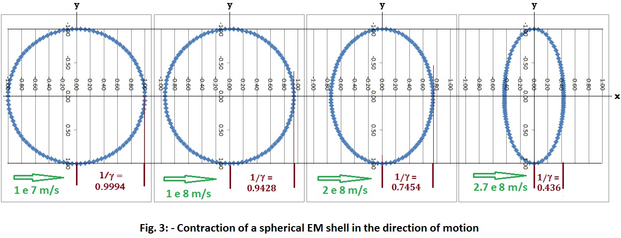
The
circumference of the sphere is found to get smaller and smaller with velocity,
proportional to SQRT(1-v^2/2c^2), while preserving the total number of
concatenated segments at 100. The height of the sphere perpendicular to travel
doesn’t change, but the length of the sphere in the direction of motion along
the x-axis shortens by SQRT(1-v^2/c^2), i.e. 1/g, which is the amount anticipated by the Lorentz
contraction. The contraction occurs for a different reason than one might
expect – the sections at the front and back of the object close to the x-axis are
the ones contracting, and this shortening pulls the ends closer together. This
gives us a picture of the proportional change in the shape of the shell with
velocity.
The
sum of the one-way wavelengths of the EM around 360 degrees of circumference
also adds up to a net shortening of SQRT(1-v^2/2c^2), which would be what would
be expected if the height remained constant but the width shrinks by the amount
of the expected Lorentz contraction.
Explanation of Time Dilation in a
Moving Particle:
If we examine the one-way propagation time
of an EM wave across each segment when the shell is moving at velocity V, we
find that the propagation time around 360 degrees is now increased. If we take
the sum of the one-way propagation time across each contracted segment, based
on the calculated speed of light at the given angle for that segment, we find
that the beam completes our 100m example circuit in:
3.3333333E-07
seconds, v = 0 m/s 3.3333358E-07 seconds, v = 365 km/s
And
we find that: 3.3333333E-07 x g
= 3.3333358E-07
So the propagation time has increased by g,
and this is after accounting for the circumference shrinking by
SQRT(1-v^2/2c^2). If we consider the natural period of the electron to be the
oscillation period of the standing wave back and forth across the shell, then
this oscillation period t will naturally increase with velocity by the Lorentz
factor g. This result has been confirmed
experimentally, for example in the Ives-Stillwell experiment of 1938.
2 Ives used the transverse Doppler
effect to confirm that hydrogen canal rays had their spectral line emissions decrease
in frequency with velocity. This follows the relation:
f’= f*SQRT(1-v^2/C^2).
In
Ives’s paper, he explains this effect based on the theory of Lorentz – it is
not “time” that dilates, but rather, the mechanical oscillation period of the particle.
So
in that sense “time dilation” could be considered a misnomer. This result also
suggests that there is no need for the electron to loose energy with velocity –
the lengthening of the period of these “atomic clocks” is a consequence of the
increased time required for the spherical waves to travel around the
circumference. The alternative would violate conservation of energy.
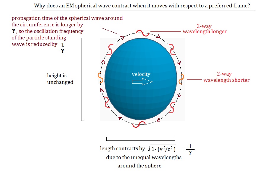
This
model can all be summarized in the diagram below:
References:
1)
Marett, Doug, “Schrodinger’s Wave Model of the Atom – A
Physical Interpretation.” Conspiracyoflight.com website. April, 2022.
2)
Ives, Herbert, Stillwell, , G.R., “An Experimental Study of the Rate of a Moving
Atomic Clock.” JOSA Vol. 28,
No. 7, 1938, P. 215 – 226
3)
Lorentz, Hendrick, “The Michelson-Morley Experiment and the
Dimensions of Moving Bodies.” Nature,
Volume 106, Issue 2677, pp. 793-795
4)
See Appendix for more details.
Appendix – Speed of light calculation in the dielectric light path:
Calculation of the angle-dependent one-way
speed of light on a light path, such as the arm of an interferometer, moving
with respect to a preferred frame, has previously been discussed in the work of
Lorentz. In 1921 he offered the following equation to express this: 3
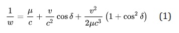
Where
w = the speed of light in the arm, u = refraction index, v the velocity with
respect to the frame, and c the speed of light in the preferred frame. This
equation is somewhat accurate, with small errors in the 0.5 m/s range, but
encounters larger errors when n > 1. It also doesn’t include the Lorentz
contraction which must be added later to the calculated length of the arm.
To
try to overcome these deficiencies, we derived a new equation as follows. If we
start from Fresnel drag equation used by Lorentz in similar calculations, we
find it can be re-expressed as:
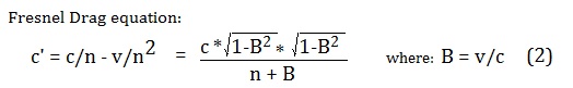
C’
= velocity of light in the arm, v = velocity of the arm with respect to the
preferred frame, and n = refractive index of the arm, angle to the wind is 0.
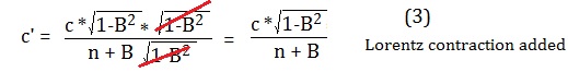
If
we now add the Lorentz contraction to the denominator, it cancels out with the
equivalent amount in the numerator, leading to the simplified version for the
speed of light in a Lorentz contracted arm at angle 0 to the wind.
We
then correct for the angle to the wind by adjusting the denominator v by the
factor cos(q):
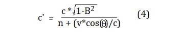
This
new equation (4) has been tested in a large number of interferometer
simulations and it predicts exactly zero fringe shifts for the motion of
interferometers with respect to space as is called for by Lorentz’s theory.
This includes for interferometer experiments with RI >=< 1.
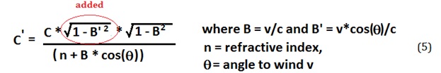
The
equation used in this paper then corrects equation 4 back to the Lorentz
contraction (LC) free version, since the LC is what we are trying to determine
in Schrodinger’s moving spherical waves. To get the correct values from 0-360
degrees, an expression shown in red is added to cancel out the angle- dependent
LC that was effectively built-in to
equation 4.
From
this the wavelength of the concatenated sections of our moving spherical waves can
be calculated using C = f * lambda.