|
|
|
|
|
|
|
|
|
|
|
Two Laser One-Way Velocity of Light
Interferometer
|
|
|
|
|
| |
|
Arm 1
Length[ L]
|
|
Refractive Index Arm 1
|
|
c' (with wind):
|
c" (Against Wind):
|
|
|
Arm 2
Length [L]
|
|
Refractive Index Arm 2
|
|
|
|
|
|
aether
wind [V] (m/s)
|
|
light l (m)
|
|
l' (into wind):
|
l" (against wind):
|
|
|
Lorentz Contraction [1/g]:
|
|
Freq. @ 632.8nm
|
|
|
|
|
| |
|
|
|
Fringe Shift Due to Path Effect:
|
Fringe Shift Due to Clock
Effect:
|
|
|
Method 1:
|
Laser
1
|
Laser
2
|
|
|
Angle to
Wind:
|
Arm 1 forward Time
|
Dt Arm1-Arm2 (s)
|
Fringe Shift:
|
[t] (s)
|
[t] (s)
|
|
|
0
|
|
|
4p*(L/l)*(v/c)
|
|
|
|
|
0
|
|
Fringe Difference:
|
|
[sin(q)] for 180 deg.
|
[sin(q)] for 180 deg.
|
|
| |
Arm 2 forward Time
|
|
|
|
|
|
| |
Arm 1 forward
|
Dt Arm1-Arm2 (s)
|
Time Difference:
|
sin(q)/2 for 90 deg.
|
sin(q)/2 for 90 deg.
|
|
|
180
|
|
|
|
|
|
|
|
180
|
|
Fringe Difference
|
|
Velocity of
Table m/s
|
Velocity of
Table m/s
|
|
|
|
| |
Arm 2 forward
|
|
|
|
|
|
|
|
|
Method 2:
|
angular
velocity [wrot] Laser 1
|
angular
velocity [wrot] Laser 2
|
|
|
|
|
Angle to
wind:
|
Phase at laser1 c*t/l
|
Phase at Det. f*t+L1/gl'
|
Fringe Shift:
|
|
|
|
|
0
|
|
|
4p*(L/l)*(v/c)
|
radius Laser 1
[L] (m)
|
radius Laser 2
[L] (m)
|
|
| |
Phase at laser2 c*t/l
|
Phase at Det. f*t+L1/gl'
|
|
|
|
|
|
0
|
|
|
|
Vspin Laser 1
(m/s)
|
Vspin Laser 2
(m/s)
|
|
| |
Phase at laser1 c*t/l
|
Phase at Det. f*t+L1/gl''
|
Time Difference:
|
|
|
|
|
180
|
|
|
|
Dt on Laser 1 (s)
|
Dt on Laser 2 (s)
|
|
| |
Phase at laser2 c*t/l
|
Phase at Det. f*t+L1/gl''
|
|
t*(1/(1-v^2/c^2)*(L/2c^2)*V*wrot*sin(q)
|
t*(1/(1-v^2/c^2)*(L/2c^2)*V*wrot*sin(q)
|
|
|
|
|
180
|
|
|
|
|
|
|
|
|
| |
|
|
|
fringe
shift on laser 1 due to Df
|
fringe shift on
laser 2 due to Df
|
|
|
|
|
Measurement
t (s):
|
Distance between lasers (m)
|
Change in Phase 0-180:
|
Final Dfringe:
|
t*(1/(1-v^2/c^2)*(L/2cl)*V*wrot*sin(q)
|
t*(1/(1-v^2/c^2)*(L/2cl)*V*wrot*sin(q)
|
|
|
|
|
|
Path-Clock Effect:
|
|
|
|
| |
|
Change in Phase 0-180:
|
|
Dfringe laser1 - laser2:
|
Dt Laser1 - Laser2
|
|
| |
|
|
|
|
|
|
| |
|
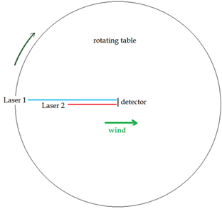
Why Can't a One-Way Velocity of Light Experiment Detect an
Aether Drift even if the Aether Exists?
|
|
|
One-way velocity of light experiments
fail to detect an aether drift since any fringe shift due to a difference in
the one way velocity of light is cancelled by a shift in the clock frequency
of the laser. This example describes what happens when two synchronized
lasers are at different distances from the same detector, where their
respective beams interfere. If the table is rotated so the lasers go from
parallel to perpendicular to the aether wind (rotated 180 degrees), a fringe
shift should arise due to the path length differences and the changing speed
of light in different directions. However, this fringe shift is exactly
cancelled by a change in the clock frequency of each laser, due to a
mechanical time dilation effect predicted by Lorentz. This is regardless of
the position of each laser on the table. Different positions can be simulated
by changing the arm lengths for each laser above. A negative length value
switches the laser to the right side of the table in the diagram. Green
values are adjustable -the refractive index of the arms and the table edge
rotation velocity can also be altered, as can the wavelength of the laser
light and the velocity of the aether wind. Hit update for the new values to take
effect. Two different methods are used to calcualte the path fringe shift -
method 1 uses the propagation time along each arm; method 2 counts the
wavelengths along each arm at the measurement time, yielding the same result.
To avoid errors, a small value should be used for the measurement time, which
is distinct from the rotation time [t] used in the laser clock effect
calculation.
|
|
| |
| |
| |
| |
| |
| |
| |
| |
| |