Interference of
Light Beams from Two Independent Lasers.
copyright
(2010) Doug Marett
Paul Dirac in his book "The Principles of
Quantum
Mechanics" has claimed quite famously that the interference of two
independent light beams can never occur. He stated that "the wave
function gives information about the probability of one photon being in
a particular place, and not the probable number of photons in that
place." In order to
explain why photon interference does not lead to a violation of the
conservation of energy principle when there is interference of one
photon with another, he instead established a new understanding, based
on the idea that a photon can only interfere with itself. And he states
quite categorically that "interference between two different photons
never occurs." 1
An experimental proof that two independent
light beams can form an interference pattern was first demonstrated in
1963 by Mandel and Magyar. 2
Mandel and Magyar actually used very short
pulses of light from two independent ruby lasers that are fired
simultaneously - depending on their phase relationship they form an
interference pattern that can be captured on a photographic plate much
like the Young Interference experiment. It is not necessary to go to
these extremes to demonstrate this kind of interference - although the
two beams may not form a stable pattern that is visible to the eye,
they do readily form a beat frequency between them that corresponds to
the rapidly changing phase relationship of the two interfering beams -
so we are essentially detecting a rapidly changing interference effect.
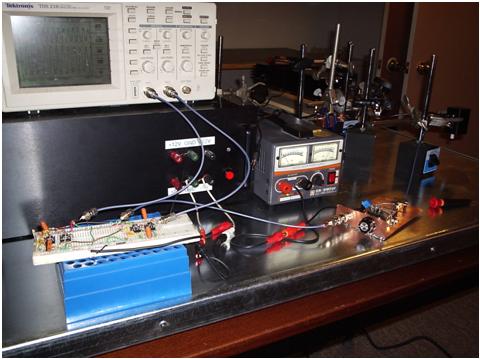
To do this, we start with two independent, frequency-stabilized HeNe
lasers that are arranged so that their beams overlap at a photodetector
similar to the arrangement shown in Fig. 1 below:
Fig. 1:
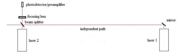
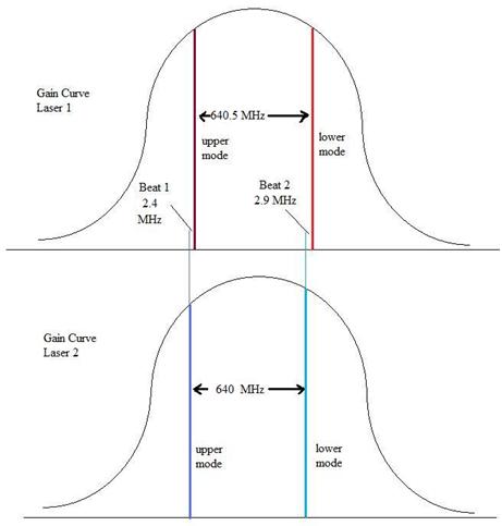
The lasers emit two modes each. The mode
spacing for laser 1 was experimentally determined to be ~640.5 MHz. The
mode spacing for Laser 2 is ~640.0 MHz. The gain curves for the two
lasers are shown below. The upper and lower mode from each laser are
perpendicularly polarized (if one is horizontal, the other is vertical).
Fig. 2:
We have essentially two modes emitted by
each laser, and the two sets of beams meet at the beam splitter, where
they are deflected into the photodetector as a total of four modes. Two
beat signals can be seen at the photodetector by displaying the
resulting signal on an oscilloscope; one is at around 500 KHz, and the
other is around about 10 MHz (which will be found shortly to be two
closely overlapping signals at around 10MHz, differing by around 500KHz
between them). If one laser is tuned so that the modes track
across the gain curve towards the modes of the other
laser, one can completely null out the beats (temporarily at
least, frequency shifts due to heat
make it oscillate across the null point).
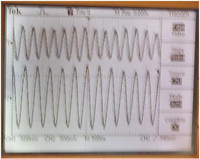
Fig. 3:
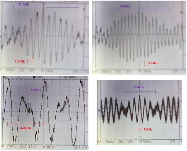
However, if one now tunes away
from this null point, what is found is that the lower beat
remains consistently at around 500KHz (once it is visible), while the
upper beat goes from say close to zero to up to 100 MHz, before it is
lost out of the bandwidth of my amplifier. Included are the four
screenshots from the oscilloscope to show this happening.
A polarizing filter is put in
front of the photodetector and rotated to see how
it changes the signal. It
is found that when the polarizer is at about
zero degrees, the upper beat is at a maximum and the lower beat is
invisible. At 45 degrees, the lower beat is at a maximum and the upper
beat is weaker. At 90 degrees, another weaker signal with a frequency
of about the upper beat frequency is visible. After considering this
behaviour it becomes evident that perhaps the mode spacing difference
between the lasers is small, and there are three beats here, two at
about the same higher frequency and one at ~500 KHz, the former one
being some overlap of two
closely spaced frequencies. One of these higher frequency beats is
difficult to see without the polarizer since it is being swamped by the
other signal of close to the same frequency.
In order to try to explain
this, an excel spreadsheet was prepared of the expected
frequencies where one can adjust the difference in the cavity
lengths, and it is found that at a cavity length difference of
just 0.08%, the two upper beat signals will always differ by ~500 KHz,
regardless of where on the gain curves they are. So what is
suggested is that this lower beat signal corresponds to the difference
in the mode spacings of the two lasers, which must be ~500 KHz (i.e. ~
640MHz and 640.5 MHz). This beat is then either a sub-beat of the two
upper beat signals in the RF range, or it could be the beat signal
between the two UHF beat signals - in both cases they should have a
maximum intensity in a plane half way between the vertical and
horizontal mode alignments (i.e. at 45 degrees) which is
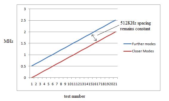
where it is found. In figure
4 below is a graph made from an Excel spreadsheet -
the test numbers are actually a number of different possible
frequencies that can exist between the two sets of modes. What one
finds is that regardless of where the different sets of modes are for
laser 1 and laser 2, on beating together, they always result in a
sub-beat frequency of around 500KHz (in our actual case, 512 KHz) which
corresponds to the difference in the mode spacings between the two
lasers.
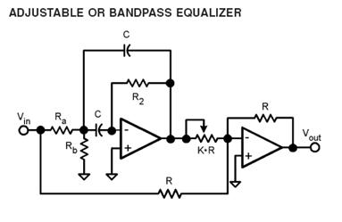
Fig. 4:
To
demonstrate that the higher frequency beat signal is in fact an overlap
of two beat frequencies close in frequency, it was necessary
to constructed a set of active filters capable of isolating
them from one another. The circuit used was the active filter in the
LMH6628 data sheet. I used two sets of LMH6609 chips, as shown in Fig.
5 below:
Fig. 5