        Construction of an All-Fiber-Optic Michelson Interferometer Doug Marett 2012 pdf version is available here YouTube videos associated with
this article:
part1,
part
2 Introduction A
Michelson interferometer using fiber-optic cable poses unique technical
challenges. The principle problem is that when laser light is made to
split into two separate paths through single mode cable, and then are
re-united at a coupler, the co-travelling beams emerging at the
detector are no longer capable of interfering with one another. This is
entirely different than the situation with the fiber-optic Sagnac
interferometer, where the co-travelling beams can go for kilometers
through single mode cable and still interfere perfectly. This
problem arises because of two issues – one is the coherence length of
the laser compared to the length of the optical paths, but second, and
more important, is the issue of maintaining the state of polarization
of the separate beams in the fiber. An optical beam travelling in a
single mode fiber will undergo random changes in birefringence induced
by stress, temperature changes, or vibration. The end result is that
the returning beams in the Michelson interferometer won’t maintain
their original state of polarization, making interference impossible.
There are two strategies that can be used to get around this problem.
One is to use polarization-maintaining fiber throughout the optical
system. Due to the high cost of PM fiber, this strategy is often
unattractive. An easier approach is to use what is called a Faraday rotator mirror
(FRM) to reflect the light back at the end of each interferometer arm.
The FRM serves as a phase conjugate mirror by creating a phase delay of
90 degrees. This feature allows the mirror and the return path to
automatically compensate for any birefringence induced in the beam
during the first half of its travel down the arm. Although FRM’s can be
quite expensive from some of the optical suppliers such as Thorlabs and
Edmund Optics, lower cost FRM’s of suitable quality can be purchased
from Chinese optical supply companies. The
coherence length issue can be dealt with by selecting an appropriate
laser source. In this project we chose a distributed feedback (DFB)
infrared laser diode as our optical source. DFB lasers generally have a
narrow line width (typically 10-4 nm)
and thereby
have a coherence length of several meters. This is significantly
improved over a Fabry-Perot type laser which typically has a coherence
length on the order of a few cm. The DFB laser has the drawback of
temperature dependent frequency response, which can cause fringe drift
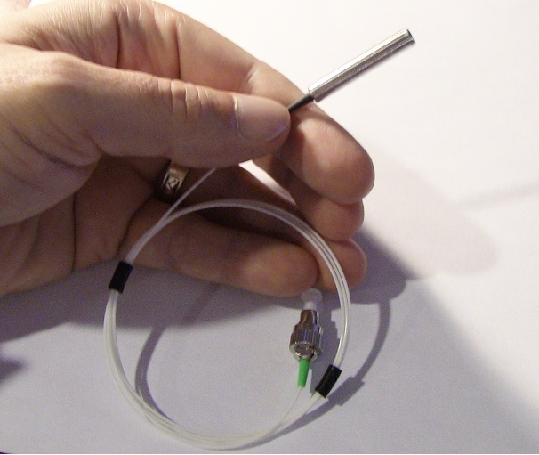
over time when the temperature is not constant. Fig.
1: A Faraday
Rotator Mirror:
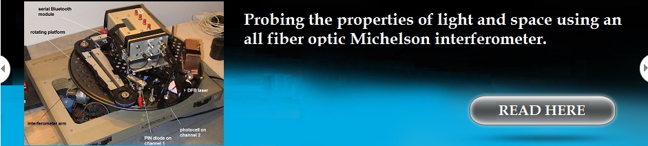
Construction and Materials Used: A diagram of the fiber optic Michelson interferometer is shown below. It consisted of only a few parts. On the left side of the SM 2X2 coupler was mounted a 1 mW 1310 nm DFB laser with an FC connector, the other port on the left was a FC mounted PIN diode detector. On the right ports we had two Faraday Rotator mirrors, each with a SM cable length of 1M. Since the 2X2 coupler also had cable lengths of 1 m on each side, the total arm length for each side was 2 m to the mirror. Fig. 2: 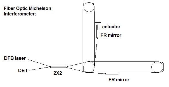
While
one mirror was affixed to the mounting platform, the other was bonded
to an electromechanical actuator to stretch the fiber by a fraction of
a wavelength at a low pre-defined frequency. The purpose of this was to
oscillate the phase position of one of the returning beams with respect
to the other, thereby generating a fringe shift at the oscillation
frequency. The completed fiber optic Michelson interferometer is shown
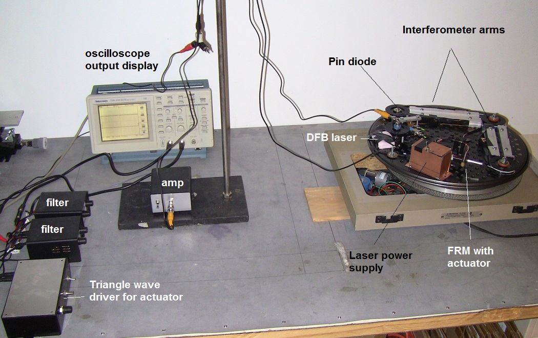
below. Fig. 3: The experimental setup
The
interferometer was tested as follows – the power supply was turned on
and supplied about 1.2V to the DFB laser module. The electromechanical
actuator was started by applying around a 25-40 Hz signal to it (signal
amplitude was 4-30V). The signal height of the triangle wave generator
was adjusted to control how many wavelengths of distance the actuator
would move based on what was viewed on the oscilloscope. Briefly, if
the actuator stretches the length of one arm by ½ a wavelength, then
the phase at the output should go from in phase to out of phase,
assuming the beams are phase aligned to begin with. This should
generate an output signal with the same period as the input triangle
wave. If the actuator moves by one wavelength, then the phase should
shift by two periods for every period of the triangle wave.
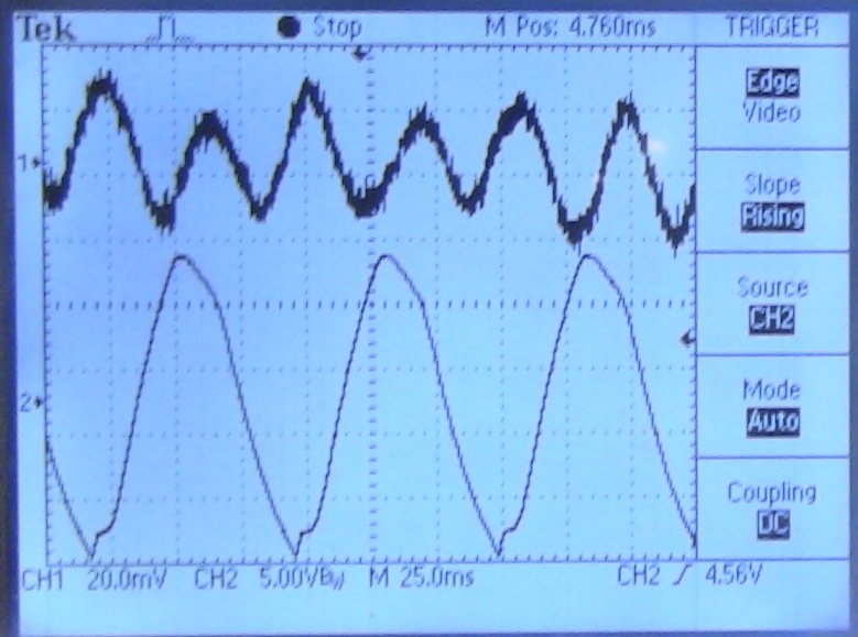
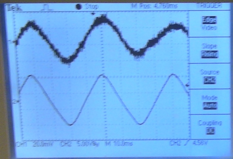
Some
examples of what this output looks like are shown below. The triangle
wave signal was started at around 25VAC as shown on channel 2 of fig.
4A. The output from the PIN diode (after amplification and filtering)
was at about 2x the frequency of the drive signal. This would then
suggest that the actuator is stretching the control arm of the
interferometer by around 1.3um per stroke.
Fig. 4A Two fringe periods per triangle wave period. Conditions: 33Hz drive, 25VAC.
In
our second example, shown in figure 4B, the triangle wave generator is
set at around 15VAC as shown on channel 2 in the figure. The output
from the PIN diode is at about the same frequency, suggesting that we
are stretching the control arm by around 0.65 um per stroke.
Fig. 4B One fringe period per triangle wave period. Conditions: 40 Hz, 15VAC.
It
seems pretty clear then that we have succeeded in getting interference
of the two beams at the detector using single mode fiber optic paths
and Faraday Rotator mirrors. So this strategy works and is considerably
less expensive than the PM fiber method. Further Improvements to the
Interferometer – Wireless data transmission
For
my purposes, I wanted to use this interferometer to replicate two
well-known experiments testing Special Relativity – namely the
Kennedy-Thorndike experiment of 1932 and the Shamir and Fox experiment
of 1969. Since both of these experiments require rotating the
interferometer to various positions, the wires connecting the device to
the electronics as shown in Fig. 2 become an impediment to rotating it
freely. In order to do this, it was necessary to use some form of
wireless data logging to get the data out of the PIN diode and into a
computer for analysis. I ended up constructing my own battery powered
data logger using a PIC16F777 microcontroller. This device is a little
too complicated to describe in detail – briefly, it used the A/D inputs
from the microcontroller to log data from two ports – each port can
sample at up to 300x per second, and this data is sent in real time out
to a two wire port. I used a simple amplifier on the input of one port
to amplify the weak signal from the PIN diode up to the 0-3.7V level
readable by the A/D.
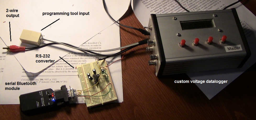
Figure 5: Custom Data-logger under construction
In
order to get the two wire ASCII data output to communicate with my
computer, I had to implement a MAX232 chip on the output to interface
with a serial Bluetooth module. The circuit used for the MA232 is shown
here. For the serial Bluetooth adapter, I used the USconverters
UCBT232B, and paired it with a low cost Bluetooth dongle on my host
computer. To receive the ASCII data, I used Putty as the terminal
program operating at 230,400 baud. The data flow is initiated at the
data logger using a menu switch, the data then flows into the Putty.log
file. Once complete, this file is converted into a .csv file which can
be easily opened in Excel.
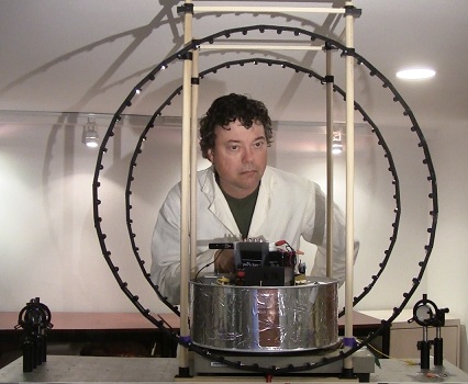
This strategy eliminated the data output wire from the interferometer. The triangle wave input was eliminated in this second version, since the experiment calls for rapid rotation on a platform and this in and of itself will generate an actuating signal simply due to the rotational motion. These actuating signals are either: a) vibration induced actuations (artifacts) or b) Fringe shifts of interest which are orientation dependent , which may or may not be present. The completed interferometer on its rotating platform with the wireless data logger mounted is shown in Figure 6: Fig. 6: 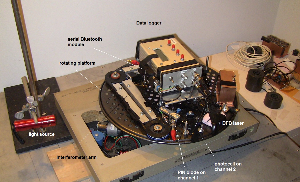
The
purpose of the light source and photocell is so that the data on
channel 2 monitors the rotation of the platform. A blip is created in
the channel 2 data every time the photocell rotates past the light
source. In this way the data received on channel 1 can be correlated
with the data received on channel 2, which is essentially the cardinal
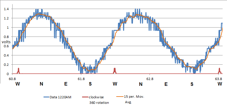
direction data. An
example of data received wirelessly from the interferometer while it
was rotated at around 40-60 RPM is shown below in Figure 7. The sine
wave output from the interferometer (blue) is a rotational stress in
the fiber optic cable that amounts to around 0.2 of a fringe and has a
period of once per rotation. The red output marks when one arm of the
interferometer passes west as the device rotates clockwise. Based on
the known height of the stress signal, the noise floor is at around 1/60th
of a fringe. Based on the length of our interferometer arms and the
resolution possible, this puts our interferometer at a comparable
resolution to the one used in the original Kennedy-Thorndike
experiment. Figure 7:
Similar
to the Kennedy-Thorndike experiment, we observed no additional signals,
such as those expected for certain ether theories (such as
Miller, or
ether theories predating Lorentz’s exact theorem of corresponding
states) which would call for a signal with a period of ½ the rotation
period. However, this result is consistent with the predictions of
Lorentz ether theory (1904) or special relativity (1905). A theoretical
discussion of this outcome with simulations is available here.
This result is also distinct from the positive
result claimed for a somewhat similar Michelson interferometer built by
Cahill
in 2007. Further, because this interferometer uses arms with a
refractive index of 1.47, the result is consistent with the outcome of
the Shamir and Fox experiment of 1969.
Conclusions I
believe we have shown that it is possible to construct a fiber optic
Michelson interferometer using single mode cable that is capable of
detecting quite small fringe shifts, on the order of 1/60th
of a fringe. The use of low cost Faraday rotator mirrors is an
effective way to achieve this result without going to all
polarization-maintaining fiber.
About the Author: |