Magnetic
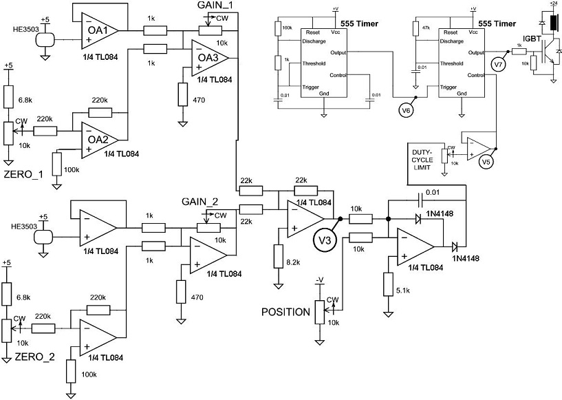
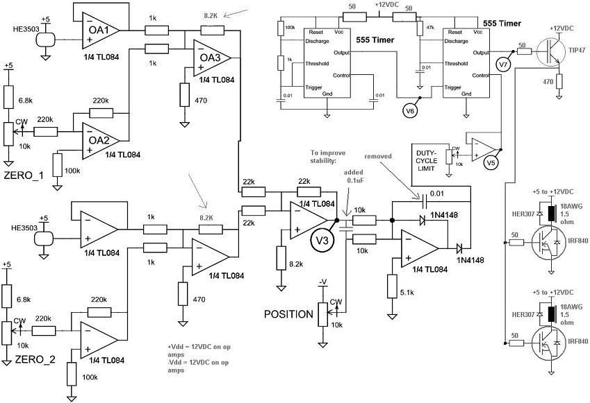
Levitator D.M. Marett (2008) Magnetic levitation is very useful in experiments where one wants a near-frictionless bearing for a motor or some other spinning device. The idea is that your rotor literally hangs in the air by magnetic forces. Usually this works if you have a circuit that generates a magnetic field to attract the magnetic end of your rotor, but can also sense its proximity, so if it gets too close, it will reduce the attraction. When it gets too far, it increases the attraction, and so on. With a circuit capable of changing the field strength at high speed, the distance of the rotor to the electromagnet becomes stable. I decided to build such a device for my own experimental work. A very good circuit was provided at the following website: http://my.execpc.com/~rhoadley/magsus.htm In the version they provide, the circuit is shown in parts. Below is the final circuit that can be gleaned from their webpage: Fig. 1: The circuit that I completed, was a little modified. This circuit is seen below: Fig. 2:
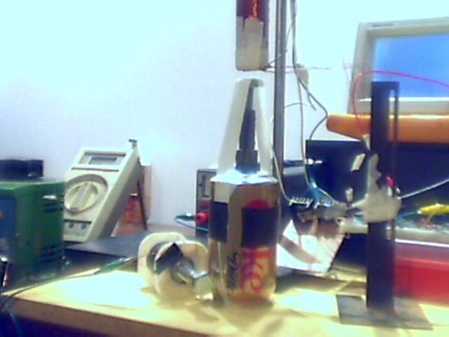
Construction of the Electromagnet: I used two IRF840 N-channel FETs into two coils, co-wound on the same laminated form. This allowed double the magnetic field possible with one HEXFET only, and helped reduce the heat. 1) The coil was made with 4 layers of #18 AWG wire, wound in two coils, on a 3/4 inch square laminated transformer iron core, approximately 9 inches long (each coil was 4.5 inches long by 4 layers thick). 2) The coils were powered by one IRF840 each. A TIP47 transistor was used to drive them, since they appeared to require a lot of gate current. 3) The hanging iron objects tended to oscillate quite a bit under the coil, leading to them falling down. To remedy this, a capacitor was added at V3, and one cap was removed. This improved the stability quite a bit. 4) The Hall effect sensors were placed on each end of the electromagnet. They were oppositely set up so that their voltages cancel at V3. At the output of the last diode (V4) the voltage is +10V when the two hall detectors read the same, or drops to 0V when V3 is closer to zero than the position voltage. The position control controls how far away the object is from the magnet, and the duty cycle controls how long the magnet is on each duty cycle. The device can suspend up to 108 grams - iron is sufficient, magnets are too unstable. In order to make the rotors rotate, an eddy current drive was set up, using a coil of #26 AWG wire wrapped on some iron nuts and bolts. Transformer iron did not work - a straight bolt with the bolt on the far end was the essential configuration, as is described at: http://www.coolmagnetman.com/magacmot.htm The final setup with a rotor made from a bolt and a coke can is shown below. Fig. 3:
Videos of the magnetic levitator in action can be found at: http://www.conspiracyoflight.com/maglev/magneticlevitatorvideos.html
|