        A Temperature
Data
logger using the Microchip PIC16F777 Doug Marett, 2012 pdf version is available here
This is a brief note
about the design and construction of a temperature sensor using a
thermistor,
and operational amplifier, and the PIC16F777 microprocessor as a data
logging
module. Part 1: Converting the
variable resistance of a thermistor into a varying
voltage readable by the PIC processor: Fig. 1:
We used the
above circuit. The thermistor was one selected
from my junk-box which had a room temperature resistance of around 10K.
To simplify matters, we chose a rail to rail
single supply OP-amp in the non-inverting configuration that would work
off the
5V supply of our PIC processor circuit. The voltage divider that the
thermistor
forms a part of, generates a temperature dependent varying voltage at
the
non-inverting input in the 2 – 2.5V range, this ultimate value
dependent on the
choice of the resistor Rd in the divider – I selected 9.2K since this
would end
up giving me around 4.5 volts at the output of the op-amp for a narrow
range
near room temperature. Since the amp has a gain of 1+ R2/R1, with the
values
chosen we have a total gain of 2, which gives a resolution of around
8mV per 0.1
deg. C. This works well in the 15 – 25 deg. C range – for a broader
range Rd
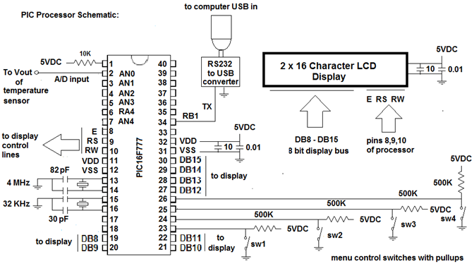
would need to be adjusted to a different value. Part 2: The
Microcontroller Interface:
Shown below is the
microcontroller interface. The Vout of the temperature sensor goes into
AN0
(pin 2) of the PIC16F777, which is the first A/D input line. The
voltage is
sampled once each second, and every minute the 60 readings are averaged
and
sent to a host computer via a serial output on pin RB1. The data is
sent in
ASCII format including a time stamp and the measured temperature value.
Only
two wires are necessary, TX and GND. Which connect to an RS232 to USB
converter
which can then be conveniently connected to a computer USB input. The
data baud
rate is set to 9600 baud, 8,N,1. Fig.
2:
The PIC is
programmed with a software routine using MPASM
assembly code which is too long to describe in detail here. Briefly, it
includes a time of day clock and a routine to sample the data and
convert the
values, as well as a control routine for an LCD display that is menu
driven
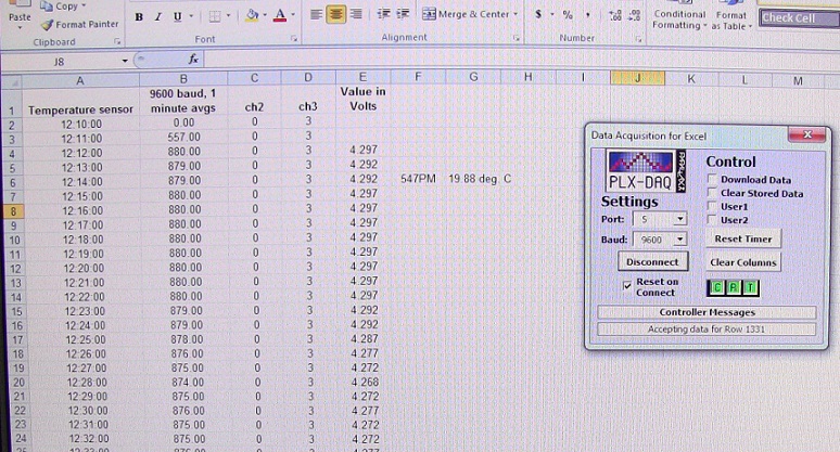
using 4 push buttons. Part 3: Collecting
the data directly into Excel.
Since it is highly
convenient to have the data collected put into an Excel spreadsheet
format for
analysis and presentation, we sought to design our data logger so that
it would
send the serial USB data directly into a spreadsheet in real time. This
was accomplished
using a program freely available on the internet called PLX-DAQ. This program
is designed to accept ASCII data sent through
a serial USB connection as long as the data train conforms to their
prescribed
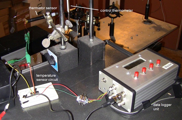
format. Fig. 3: The completed
temperature data
logger:
Fig.
4: Screenshot of real time data being received serially into
Excel using PLX-DAQ.
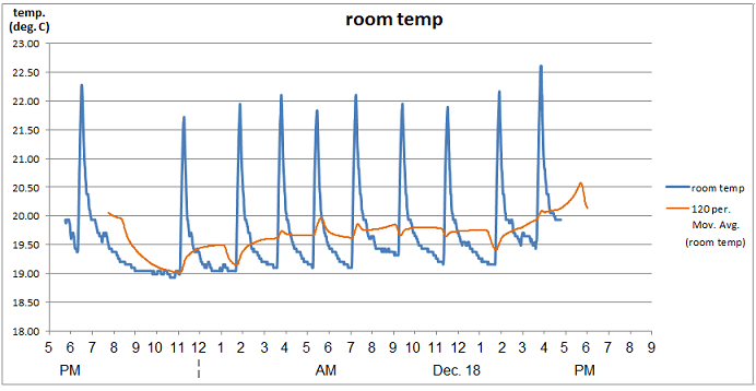
Part 4: The end result
– real time temperature data! Fig. 5: The final data
plotted in Excel:
As can be seen
above is an example of data collected every
minute using the data logger over a period of 24 hours. The logger
collected
86400 values which were averaged to 1440 minute values delivered in
real time.
The data was taken in early winter, so the temperature spikes are due
to the
heating cycles of a forced air gas furnace heating the room
periodically.
Outside temperature was around 9 deg. C during the day on Dec. 18th.
|