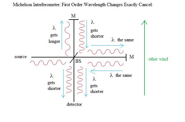
        A Replication of the Cialdea One-Way Speed of Light Experiment Copyright (2010) Doug Marett a .pdf version of this paper is available here Introduction: Historically, most interferometer tests of Einstein's second postulate on the constancy of the speed of light have used methods where the experiment is sensitive to second order effects. What this means is that the phase shift seen at a detector between two beams that have travelled different paths in the interferometer is proportional to the square of the velocity of any hypothetical ether wind that the apparatus is moving through, divided by the square of the velocity of light (v2/c2). In a first order effect, the phase shift would depend on the ratio (v/c) instead. As one can see, "first" and "second" refers to the exponent applied to the velocities in each ratio. An example of a first order difference in an interferometer would be one that depends on a wavelength difference in the different paths. If we look at a Michelson Interferometer as shown in figure 1: Fig. 1:
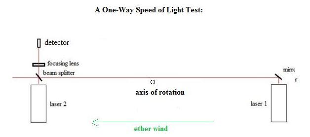
Since the speed of light c = f l, if the speed of light increases (c+v) due to an ether wind velocity (v) in the same direction, the wavelength (l) must also increase to compensate. The converse is also true, if the speed of light decreases (c-v) then the wavelength must become smaller to compensate. The frequency (f) always remains the same, since a change in frequency would lead to a piling up of wavelengths or a break in the wave-train. However, what we find is that the increase in the wavelength in the upper vertical arm when the light goes to the mirror is compensated for by the decrease in the wavelength of the light returning from this mirror. In the horizontal arm, the wavelengths remain the same at first order. Therefore, at the detector, the phase relationship between the two beams when they meet remains the same, regardless of which way the interferometer is turned with respect to any hypothetical ether wind. The only difference that remains is a much smaller effect, the second order effect due to difference in the distance travelled by each beam as a consequence of the motion of the detector with respect to the hypothetical ether, which is discussed in detail in http://www.conspiracyoflight.com/M&M.html. This small difference also reduces to zero due to the effect of the Lorentz contraction as assumed in Lorentz Ether Theory (LET). One can see that if a first order difference could be detectable in an interferometer, it would be much easier to detect an ether wind if it exists, since the effect would be considerably larger. We take for example three possible sources of an ether wind: 1) The motion of the Earth with respect to the Cosmic Microwave Background radiation (CMB) which is 365 km/s. 2) The motion of the Earth around the sun, which is 30 km/s. 3) The rotation of the Earth, which is between 0-465 m/s, depending on your latitude, let's say about 365 m/s for somewhere in the USA. For a first order difference (v/c) in an interferometer, if we say for example that a large ether wind due to the CMB could cause a fringe shift of 1 fringe when the interferometer is rotated 90 degrees, then the Earth's orbital velocity of 30 km/s would cause a fringe shift of 0.082 fringes (12.2x smaller) in the same test, and the Earth's rotation would cause a fringe shift of 0.001 fringes (1000x less). For a second order difference (v2/c2) if we say for example that a large ether wind due to the CMB could cause a fringe shift of 1 fringe when the interferometer is rotated 90 degrees, then the Earth's orbital velocity of 30 km/s would cause a fringe shift of 0.0067 fringes (149x smaller) in the same test, and the Earth's rotation would cause a fringe shift of 1 E -6 fringes (1 million x less). In gravitational frame dragging theory the only ether wind that would hypothetically be detectable would be due to the Earth's rotational motion. One can readily see that a first order interferometer test would be 1000x more sensitive than a second order test for this small velocity of say 365 m/s, so the first order test has a big advantage. Most second order interferometer tests performed to date are not even sensitive enough to detect this small velocity. So what kind of interferometer could detect a first order difference? An example is shown in figure 2 below: Fig. 2:
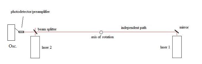
In the example of figure 2, we have two lasers that we assume under ideal conditions are of exactly the same frequency (f). The long path between laser 1 and the beam splitter is expanded in wavelength by the ether wind shown, since it is parallel to the beam. The beam of laser 2 is unaffected in first order since it is perpendicular to the ether wind. If the device is rotated 180 degrees, then the long path is wavelength contracted with respect to the ether wind, and again the beam from laser 2 is unaffected. Thus in rotation a first order phase shift can occur at the detector due to the changes in the wavelength of laser 1, and this effect is proportional to the length of this long path (this approach was theoretically criticized by Tyapkin [2], see "Discussion and Conclusions" for more details). The inevitable problem with this idea is that of synchronizing the two lasers to exactly the same frequency. Any attempt to synchronize the two lasers will close a path between them, which will cancel out the phase difference just like in the closed path Michelson interferometer. Such an experiment is considered to be impossible by Special Relativity on the grounds that is impossible to synchronize the two lasers. In reality, this is not impossible, it is just really hard to do. In this context then we wish to discuss our replication of the Cialdea [1] experiment of 1972. The Cialdea experiment is a one-way speed of light experiment similar in many ways to that shown in Figure 2. Surprisingly, the experiment is criticized by some relativists as "impossible" (Tyapkin)[2] and by others it is held up as an example of the validity of special relativity theory, i.e. http://www.xs4all.nl/~johanw/PhysFAQ/Relativity/SR/experiments.html see their section 3.2. Regardless of whether this experiment is valid on theoretical grounds, we sought to determine if it is capable of showing anything experimentally. Let's now discuss the experimental setup of the Cialdea experiment shown in Fig. 3. Fig. 3:
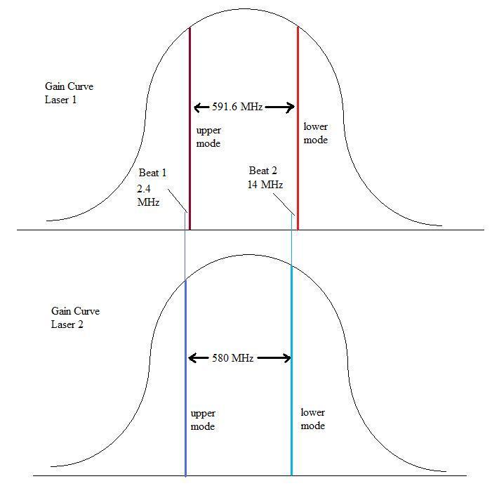
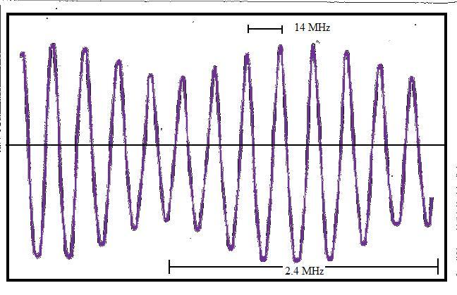
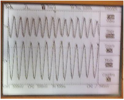
We see that the arrangement of the apparatus is effectively identical to that of our Figure 2, except that now instead of looking at a fringe shift at the detector, we are looking at the beat frequency of the two beams at a photodetector connected to an oscilloscope. This setup is already discussed in detail in a previous paper on this site on two beam interference, see: http://www.conspiracyoflight.com/LaserInterference/LaserInterference.html To apply what is going on to this specific experiment, we refer to figure 4 below. Essentially, what Cialdea did was to beat the two independent laser beams together at the photodetector by precisely overlapping them. We show the gain curves and mode spacing's that are described in the paper, and we can see that Cialdea says that in the bandwidth of his oscilloscope, it is possible to see the beat frequencies that are below 150MHz. He anticipated these beat frequencies, one between the upper modes of Laser1 and 2, and one between the lower modes of laser 1 and 2. Based on the information provided in the paper, these beat frequencies were observed to be 2.4 MHz and 14 MHz. A recreation of the oscilloscope trace reported in the Cialdea experiment is shown in Fig.5. Fig. 4:
Now, we already know that Laser 1 and Laser 2 are at slightly different frequencies - in the experiment their center frequencies differ by 2.4 MHz. This will mean that we will not be able to see any kind of stable interference pattern caused by the beating of these two lasers. What we will see is a rapidly changing interference effect (the beat signal) which is oscillating at the frequency difference between them. How does Cialdea propose to measure the first order effect in this situation? Firstly, he proposes that "the frequency of the Laser radiation depends on the orientation of the cavity" (assuming from his assumption 4 there is a reference system absolutely at rest) - see P. 823 of the paper. However, as was pointed out earlier in this paper, in such a circumstance, it is not the frequency but the wavelength that would change in response to a change in the speed of light based on the formula c = f l, so this is a questionable statement. If, on the other hand, the laser tube changed its length, due to say a Lorentz contraction, then we would expect a frequency change, but this is a different situation since if it did occur it would be a much smaller second order change and would be undetectably small in this experiment. Fig. 5 Oscilloscope trace from the Cialdea Experiment showing the beat frequencies.
Cialdea goes on to present a mathematical argument that when the device is rotated, there should arise a phase shift between the two beat signals (in this case, the 2.4 MHz signal vs. the 14 MHz signal) that will depend on the rotation angle with respect to the ether wind. The phase shift calculated in their paper amounts to (8p/3) * (L/l) * (v/c) * (radians/360) for a hypothetical ether wind of velocity v, where the wind is first parallel and then anti-parallel to the laser path (due to a bench rotation of 180 degrees). Cialdea reports that they rotated the device many times and they never witnessed such a phase shift between the two beat signals. From their equation above, a phase shift of 180 degrees would correspond to an ether wind velocity of only 45 m/s. Since they felt that they could resolve by eye fringe shifts as low as 1/50th of this displacement, then the highest possible ether wind that could exist would have to be less than 0.9 m/s. Note:
that
the equation used by Cialdea is different than a calculation of the
fringe shift caused by the time delay difference in the two directions,
that depends on the path length difference L between the two lasers
shown in Fig. 2, as well as the velocity difference of light in the two
directions due to the hypothetical ether wind. Calculated in this
manner, the expected phase shift for 180 degree rotation would be: (4p) * (L/l)
* (v/c) * (radians/360). Clearly, if this result were true, it would deal a devastating blow to all ether theories, including the gravitational frame dragging theory, that requires an ether wind of around about 300-400 m/s in the northern hemisphere due to the rotation of the Earth. Now, let's examine the experiment in detail. We will soon see that Cialdea's claims are unfounded. Initial
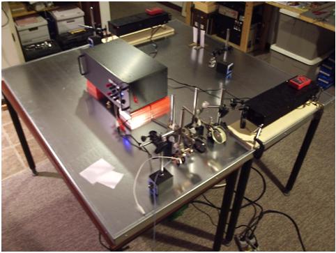
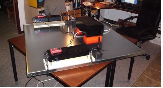
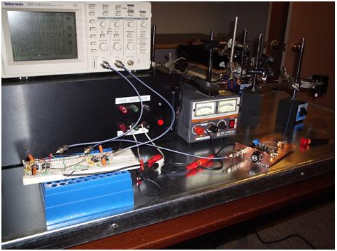
Discussion of the Experimental Method of Cialdea: First, the experimental report does not provide many details. There is little information on how the rotating bench was constructed. It does not explain how the rotating bench was rotated, or how the signal from the photodiode was sent to an oscilloscope, or whether the oscilloscope was on the rotating bench or stationary. It is claimed that the interference pattern occurs for only 1-2 seconds every 5 minutes or so, but it does not explain how the bench (2m long with 30cm Lasers on it) can be rotated 180 degrees in 1-2 seconds at a uniform speed with little prior notice (interference is random in time) while still keeping the eyes fixed on the oscilloscope trace! The reason for this very short, periodic appearance of the oscilloscope beat signals is due to the fact that the HeNe lasers used by Cialdea were not frequency stabilized. HeNe lasers tend to have their modes drift in frequency up and down their gain curves due to small temperature fluctuations in the hot laser tubes, that cause the length of the tubes to increase or decrease slightly. This causes a shift in the resonant frequency of the tubes. Due to this, the frequency distance between the modes of one laser with respect to another is constantly changing, so much so, that they will go from outside the bandwidth of the oscilloscope (say above 150 MHz difference) and drift past each other (through zero) and then on out of the bandwidth again. When the HeNe's are first turned on, this swing will occur every few seconds, and as they stabilize over 1/2 hour or more this will slow down to maybe one swing every few minutes. This is why it is hard to believe that anyone could carry out any kind of accurate phase analysis on two beat frequencies which are drifting in relation to one another in this manner. We did reproduce this phenomenon in our lab by keeping the frequency stabilizing switch off on both lasers, and verified that nothing useful could be gleaned from the traces as they zipped past each other in frequency as Cialdea describes. We must understand then that in Cialdea's results, the citing of one beat signal at 2.4 MHz and the other at 14 MHz represents merely one snapshot in time when they took the photo on page 824 of their paper. At the next time the beats show up, there frequency difference would likely be some other set of frequencies, that would also be changing over time since they are drifting in frequency in relation to one another. The repeatability of the results need to be understood in this context. Our Replication of the Experiment Using Frequency-Stabilized HeNe Lasers. Two lasers were built in the second/third week of October, 2009. A description of these lasers is this link. The experiment was set up on a rotating table. See Figure 6 below. The table consisted of a 1.5" x 4' x 4' wooden slab that was covered on its upper surface with galvanized iron sheet. The sheet served as a magnetic platform to mount magnetic bases for holding the optical components. The table was supported on a bearing system consisting of a large number of 1/2" diameter steel balls enclosed in aluminum rings. This allowed the optical table to be rotated uniformly over the surface of the underlying support table. The large metal box in the center of the table is a power supply. The length of the independent laser beam path from the mirror to the beam-splitter (Fig.2) was 1 meter. Fig. 6:
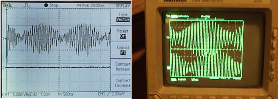
The two lasers are shown above, with the light path down the center of the table (passing behind the supply) to the beam-splitter, through a lens and polarizer, to an EOT photo-detector/pre-amplifier (ELH0033). The main RF amplifier and the oscilloscopes are out of view and are connected to the photodetector by a coaxial cable. Results: The first results were a replication of the beat pattern reported by Cialdea. This beat pattern was initially found to resemble at composite of two beat signals - a lower frequency signal of around 500KHz, and a higher frequency signal that varied in frequency depending on where the laser modes were in their gain curve, but was typically between around 1 MHz and 100 MHz. Some examples of this pattern are shown below in Fig. 7: Fig. 7: On a Tektronics TDS 210 scope and on a TDS 320 scope:
For a rotation of the apparatus on the table from N-S to E-W, or E-W to N-S (90 degrees each way) or from N-S to S-N (180 degrees) there should be no observable phase shift between the lower frequency beat signal and the upper frequency beat signal, as was the described test of Cialdea. This result was confirmed. A picture of the laser path lying on the E-W line is shown in Fig. 8: Fig.8:
Deciphering
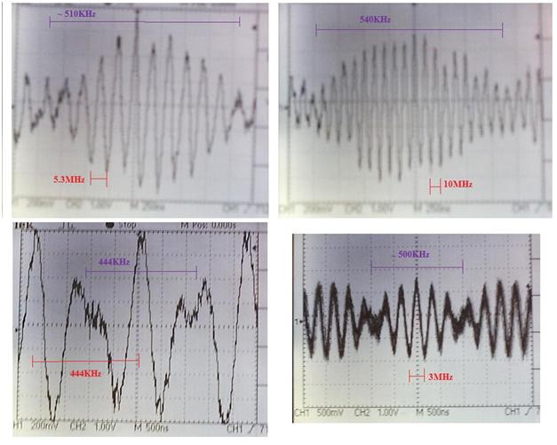
what the Cialdea Experiment was actually looking at: From my concept of what is going on, we have essentially two modes emitted by each laser, and the two sets of beams meet at the beam splitter, where they are deflected into the photodetector as a total of four modes. As was mentioned earlier, one can see two beat signals at the photodetector, one is at around 500 KHz, and the other is variable, and in one case was stabilized around about 10 MHz. If I tune one laser so that the modes track across the gain curve towards the modes of the other laser, then this 10MHz signal can be progressively lowered to 5.3MHz, then to 3MHz, then to 444KHz. However, the ~500KHz signal remains at somewhat the same frequency (measured off the screen, it is very roughly 440 -540KHz). This is shown in Fig. 9 below: Fig. 9:
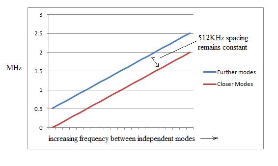
If I tune the laser modes to move away from each other, the upper frequency increases up to 100MHz and then out of the bandwidth of my oscilloscope. I put a polarizing filter in front of the photodetector and rotated it to see how it would change the signal. What I found is that when the polarizer was at about zero degrees, the upper beat was at a maximum and the lower beat was invisible. At 45 degrees, the lower beat was at a maximum and the upper beat was weaker. At 90 degrees, another weaker signal with a frequency of about the upper beat frequency was visible. This made me think that perhaps the mode spacing difference between the lasers is small, and there are three beats here, two at about the same higher frequency and one at ~500 KHz, the former one being some overlap of two closely spaced frequencies. One of these higher frequency beats was difficult to see without the polarizer since it is being swamped by the other signal of close to the same frequency. I made an excel spreadsheet of the expected frequencies where I could adjust the difference in the cavity lengths, and I found that at a cavity length difference of just 0.08%, the two upper beat signals will always differ by ~500 KHz, regardless of where on the gain curves they are. So what I suggest this lower beat signal corresponds to is actually the difference in the mode spacing's of the two lasers, which must be ~500 KHz (i.e. mode spacing's are ~ 640MHz for laser 1 and 640.5 MHz for laser 2). This lower beat is then either a sub-beat of the two upper beat signals in the RF range, or it could be the beat signal between the two UHF beat signals - in both cases they should have a maximum intensity in a plane half way between the vertical and horizontal mode alignments (i.e. at 45 degrees) which is where I find it. The below diagram is from the excel spreadsheet analysis I performed of what beat frequencies one would expect as the modes of the two lasers tracked away from each other on the gain curve. As can be seen, as the frequency difference between them goes higher on the Y-axis, the mode spacing difference (Laser 1 to Laser 2) remains the same. So the blue line corresponds to high frequency beat1, the red line corresponds to high frequency beat 2, and the difference between them remains constant at ~500KHz. The reason why the 500KHz signal remains somewhat constant is because the mode spacing for each laser is = C/(2*L), where L is the mirror to mirror distance in meters and C is the speed of light. Since the temperature fluctuations cause only slight length changes (around 1um) over short time intervals, the mode spacing's of each laser might only be fluctuating by around 3 KHz each, and since the 500KHz signal is the difference between these two mode spacing's of Laser 1 and 2, this signal will be stable within about +/- 3KHz. This sub-beat signal was isolated using a band pass filter and measured with a frequency counter, and it was confirmed that the signal fluctuates by around 1-3 KHz after the lasers are warmed up and stabilization is ON. Fig. 10:
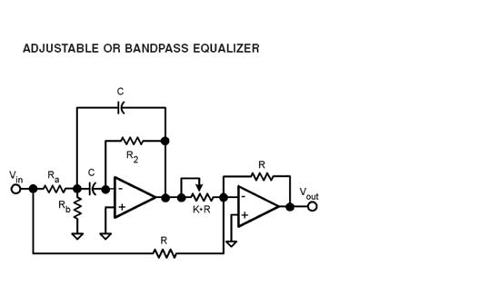
To demonstrate that the higher frequency beat signal is in fact an overlap of these two beat frequencies (red and blue), I constructed a set of active filters. The circuit used was the active filter in the LMH6628 data sheet available online, and shown in Fig 11 below. I used two sets of LMH6609 chips instead. Fig. 11:
All power supply leads (+/- 5V, except gnd) had 470 ohm resistors on them to limit oscillations. Ra = 470 ohms, Rb = 22 ohms, R2 = 2.2K, C = 200pF, K-R = 150 ohms, R = 150 and 330 ohms. The band pass was sharp with a 10X drop at 500KHz either side. The center frequencies for the two filters were set at 2.4 and 2.9MHz. A picture of the filters in the setup is shown below in Figure 12: Fig. 12:
The filters are on the breadboard. The apparatus is then adjusted so that each of the two beat signals from Laser 1 and Laser 2 fall each within the band pass of one of the filters. The output of the two filters are shown one above the other on the oscilloscope trace in Fig. 13 below: Fig.13:
One is at 2.4MHz, the other at 2.9MHz, as measured off the scope, and their intensities are not equal, which might explain why one easily swamps the other when they overlap unfiltered. This demonstrates that our observation is correct, and that the upper beat signal seen in the original traces of Figure 9 is actually two overlapping beats that differ in frequency by ~ 500KHz, and the frequency of these upper beats goes from close to zero to well over 100MHz, depending on how far apart the modes are in their gain curves between laser 1 and laser 2. This frequency can be controlled by adjusting the beam balance on one of the stabilized lasers, that then moves the two modes of that laser to a higher or lower frequency inside of the gain curve as compared to the other laser, which is held stable. The question then is, if one should expect three beat signals in this experiment, then why did Cialdea only report two? Did he mistake the lower sub-beat for one of the high frequency signals? This would seem plausible, considering that the lower sub-beat always appears as a modulation of the upper frequency in exactly the pattern that we reproduced in Figure 7. This suggests that one of the beat signals that Cialdea wanted to compare might have been buried by the other two beats and he may have compared the wrong two beats in his experiment. The two high frequency beat signals were also compared on the scope (on channel 1 and 2, respectively) to see if one would move in its phase relationship to the other as the table was turned from N-S to E-W, and vice versa, or from N-S to S-N (180 degrees). Again, no change in phase was observed in any direction. A
Positive Control Test - Changing the Path Length of One Laser: In the Cialdea experiment, although a negative result was reported, a positive test was never performed. If this experiment is to be a valid test of relativity, then one needs to show that the apparatus can actually show a phase shift when one would be expected. We are measuring a first order shift in phase between two laser beams of unequal path length. Cialdea claims that if an anisotropy (ether wind) is present, then a visible shift in phase between the two beat signals on the oscilloscope will be observed. If this premise is true, then simply changing the path length of one laser should be sufficient to cause a similar phase shift. Rather than moving one laser with respect to the other, instead, I placed a piece of glass in the beam path of one laser. The refractive index of the glass (~1.5) should be sufficient to change the phase of the first laser beam as compared to the second. and should change the phase of the independent beam at the photo-detector by slowing down the overall speed of light in the path by around 1/3000 (a 1mm thick glass slide was used). This would mimic an ether wind of C/3000 = 100 km/s in terms of the effective speed of light in the independent path. If this were an interferometer like that shown in Fig. 2, where the frequency difference between the two lasers is zero, then one would expect a classical fringe shift of 948 complete fringes for a speed of light change in the independent path of 100km/s, where the independent path is 1 meter long, and the wavelength of the lasers is 632.8 nm, and the device is rotated 180 degrees starting from parallel to the ether wind. A fringe shift of half this amount would be expected for a rotation of 90 degrees. However, this test also failed to cause any phase shift at all between the two beat signals on the oscilloscope. It also failed to cause a phase shift between the upper frequency beats and the 500 KHz sub-beat, when this was also tested. Discussion
and Conclusions: The results of the positive test for a fringe shift in the Cialdea experimental setup has shown that the device is actually incapable of showing a relative phase shift between the two beat signals, even when one should be present due to a deliberate change in the speed of light in the path using glass. The only conclusion that we can take from this is that the experiment of 1972 actually proved nothing - it is not a verification of special relativity, nor does it disprove any ether theory. The Cialdea experiment was first criticised by Tyapkin [2], who argued that the change in phase due to the change in time along the independent path between the lasers when the device is rotated would be exactly cancelled by a change in phase of the light in the laser output. Mansouri and Sexl [3] also commented on the Cialdea experiment, suggesting that Tyapkin's theoretical dismissal of Cialdea's first order experiment was incorrect. However, neither of these authors actually attempted to replicate the experiment. The problem appears to be simpler - the beat signals displayed on the oscilloscope are shifting phase already at high speed due to the frequency differences between the independent lasers. Any possible phase shift that might occur between the two beats due to an ether wind would occur over a timeframe of several seconds as the device is rotated, and if it did occur, it would immediately be lost in the rapid phase shifts of the beats, that are changing on the order of 100's of millions of times per second. The time base (sweep triggering ) of the oscilloscope cancels or obscures all of the relative phase differences that might arise due to rotation. Although Cialdea points this out, he suggests that overlapping more laser frequencies will eliminate this problem. Clearly it does not, since in practice no phase shift can be made to occur even with our positive controls. This highlights the problem with relativity experiments that attempt to prove a point with a negative result only - without at least a good positive control, how can we know that the experiment even works? Footnotes: 1) Cialdea, R., (1972) "A New Test of the Second Postulate of Special Relativity Sensitive to First Order Effects. " Lettere Al Nuovo Cimento, Vol. 4 No. 16, 1972 2) Tyapkin, A.A., (1973) "On the Impossibility of the First-Order Relativity Test." Lettere Al Nuovo Cimento Vo. 7, No. 15, 760-764. 3) Mansouri, R., Sexl, R., (1977) "A Test Theory of Special Relativity: II First Order Tests" General Relativity and Gravitation Vol. 8, No. 7 (1977) p. 515-524. |