|
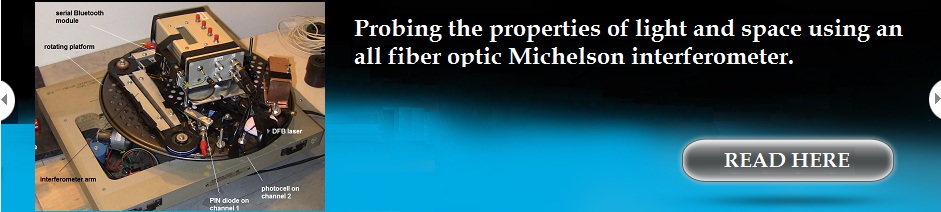
A Single Laser One-Way Speed of light
Experiment using a Standing Wave Interferometer
Doug Marett (2011)
click
here for pdf version
Introduction
A common theme often argued as contradicting
the
constancy of the speed of light postulate of relativity theory is the
apparent anisotropy of light speed in rotating frames, such as in
Sagnac interferometers. For an observer attached to the periphery of a
rotating disk, beams of light counter-propagating around the rim of the
disk will arrive back at the observer at different times. Such
interferometers can detect the slow rotation of the earth at 15 degrees
per hour, even though to the observer on the earth, the device appears
completely stationary. The
phenomenon also manifests itself in the one way propagation times in
GPS to earth-bound receivers, where the translational velocity of the
earth at 30km/s is invisible, but the rotational velocity of the earth
at 100x less becomes visible in the frame of the earth observer. This
error time has become known as the Sagnac delay in GPS. This phenomenon
has led some researchers to suspect that the Earth Centered Inertial
(ECI) frame of the earth is isotropic for the speed of light, and the
earth observers rotate through it. If this were the case, then one
would expect the one way velocity of light would differ by c+v to the
west of a rotating observer, and c-v to the east, where v is the
rotational velocity of the earth at the observer’s latitude. Still
other researchers have suggested that the velocity of the earth with
respect to the Cosmic Microwave Background (CMB) should be detectable,
since this is the only frame in which light is isotropic (a static
Lorentz ether model).
However, attempting to measure the one-way
translational speed of light with a conventional interferometer is
considered impossible. Hendrik Lorentz demonstrated over 100 years ago
that in Michelson-type interferometers any first order difference is
the speed of light in different directions will perfectly cancel out at
the photo-detector, and hypothesized that the Lorentz contraction
cancels any second order differences.
Standing wave interferometers circumvent this
dilemma. In a standing wave interferometer, one measures the position
of the standing wave with respect to the plane of a transparent sensor.
Differences in the speed of light in different directions in space
should lead to the overall wavelength of the laser beam changing, since
C=f l.
If the speed of light rises or falls in a
given direction, then the wavelength must also rise or fall (frequency
can’t change since this would disrupt the continuity of the
wave-train). This is detected as a phase difference between two
counter-propagating waves, which is ultimately detected as a position
change of a standing wave with respect to the standing
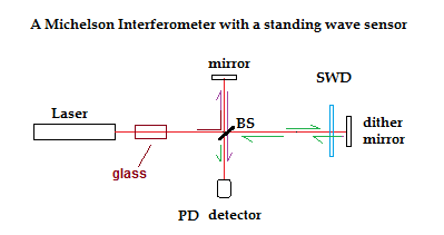
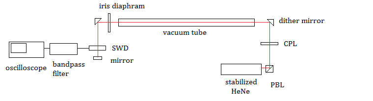
wave detector (SWD). This can best be understood by
the example below. What is shown is a Michelson interferometer combined
with a standing wave sensor and dithered mirror. To visualize the
difference between the two interferometers, imagine that a piece of
glass is inserted into the path as shown below. Since the speed of
light in the glass is lowered, the wavelength is also
lowered. Since the beam goes through the SWD
to a mirror and then returns, the standing wave formed at the
SWD will change its phase visibly as the wave crests recede through it
due to the placement of the glass in the beam. Since this
standing wave is also being re-phased by the motion of the dithered
mirror, this change in the phase relation between the two beams will
manifest as a change in the phase position of the SWD signal output
with respect to the dither signal driving the mirror, when they are
displayed together on a 2-channel oscilloscope.
Conversely, for the beams arriving at
the photo-detector (PD) , by the time they reach it they are
travelling in the same direction, and thus the phase change
caused by the placement of the glass in the beam as shown will be equal
for both beams returning from their respective arms and no net change
in their phase relationship will be visible. Thus a wavelength change
in the path common to both beams is visible in a standing wave
interferometer but invisible in a Michelson interferometer. However, if
the frequency of the laser beam changes throughout the entire system
(and thereby the wavelength) then this kind of change can be detected
even with a Michelson interferometer, as long as the two Michelson
interferometer arms are of differing lengths, since this will generate
a temporary phase shift between the beams arriving at PD. However, the
fringe shift at SWD will be greater, since the phase differences due to
the common paths will add when the beams countertravel through the SWD,
rather than canceling out when they co-travel to the PD.
Since the standing wave difference results in
a
small D.C. voltage with respect to a much larger photovoltaic voltage
from the beam in general, dithering one mirror in the optical path is
the most common method of making this phase shift visible on
an oscilloscope, since this will generate an oscillating AC signal as
the standing wave dithers through the SWD detector.
A
hypothetical aether wind would also cause a velocity change in the
speed of light and thereby a wavelength change, and this should also be
theoretically possible to visualize using a standing wave detector. In
this paper we measure this changing phase relationship at the SWD while
the entire optical table is rotated around 360 degrees. If the
wavelengths of the counter-propagating beams change as predicted, then
a phase displacement should similarly arise by rotating the table with
respect to the direction of an aether wind. A small aether wind
velocity of 336 m/s due to earth’s rotation will cause a fringe shift
at the SWD of 7 full fringes after rotating the table 180 degrees,
assuming that one path is longer in a single linear direction than the
other by 1 meter.
This experiment became possible due to our
obtaining
a high-quality standing wave detector, graciously provided to us by the
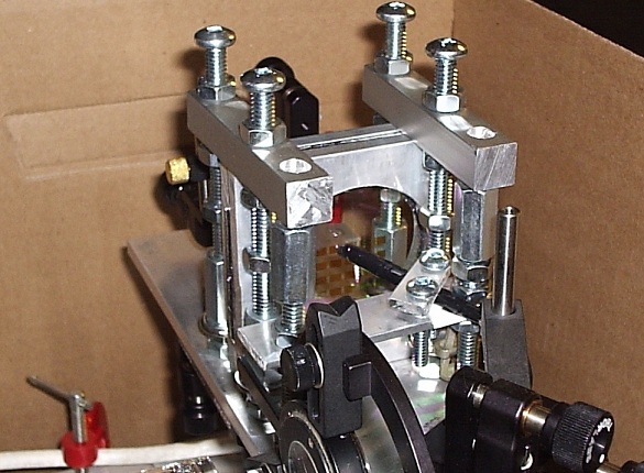
Institute of Photovoltaics, Jurlich. This sensor is a transparent NIP
photodiode array of amorphous silicon with a total of 25 independent
elements. It was designed for use at 632.8 nm, where reflections are
minimized. The amorphous layer system thickness is less than 100 nm.
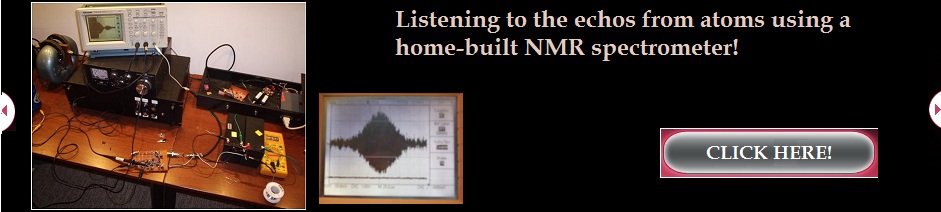
A view of the Standing Wave Sensor (SWD) in
its optical mount
Design of the Experiment
Four different interferometer arrangements
were
tested. A schematic representation of each is shown below. All of the
interferometers used circularly polarized light and CPL filters to
prevent light getting back into the laser cavity. Occasionally linearly
polarized light was also tried, with similar results. In all cases
there was one mirror which was typically dithered at 100 Hz. The
location of this mirror varied from one arrangement to another. A
frequency stabilized HeNe laser was used in all arrangements. This is
critical, since each interferometer acts as a wavelength detector. The
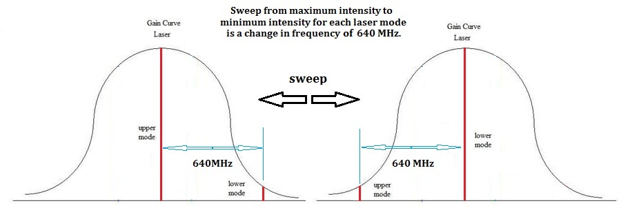
un-stabilized HeNe laser sweeps through its gain curve rapidly on first
start-up, and then progressively more slowly after warming up for ½
hour or more. When
un-stabilized, the wavelength of the laser light is constantly
changing, and thus the standing wave pattern at the SWD detector is
constantly sweeping through fringes. This is used to advantage to
calibrate the interferometers. Since we know the frequency sweep across
the gain curve for the laser (640 MHz, based on direct measurements) we
can calculate the wavelength change expected as the laser sweeps from
one side of the gain curve to the other. This value can then be
compared to the actual fringe shifts observed, and tested against an
Excel spreadsheet model of the fringe shift expected based on the
lengths of the combined optical paths. The laser can then be switched
to lock mode, where the fringes stabilize in relation to the dither
phase of the mirror oscillator.
In the first interferometer, the SWD output
was sufficiently intense to see on the oscilloscope without
amplification (around 20-50mV peak to peak). With the other
interferometers, some amplification and filtering was necessary due to
the weaker intensity of the output signal.
A 100Hz band-pass filter with a voltage gain
of 100
was used for this purpose before the oscilloscope.
Interferometer 1:
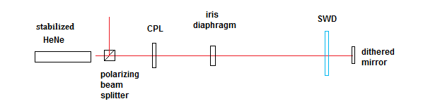
This design used a conventional standing wave
interferometer setup with a single linear path and a dithered mirror at
the far end serving as the source of the return path through the SWD.
This arrangement was found to generate dither signals from
retro-reflections that did not include the path between the laser and
the SWD detector – inserting a glass slide between the SWD detector and
the dithered mirror generated a large fringe shift, but inserting the
glass slide at other places in the beam had little to no effect. It
also did not conform to the predictions from our excel spreadsheet as
to the number of fringe shifts expected as the laser sweeps through its
gain curve. As a result of these discrepancies, this design was
abandoned.
Interferometer 2:
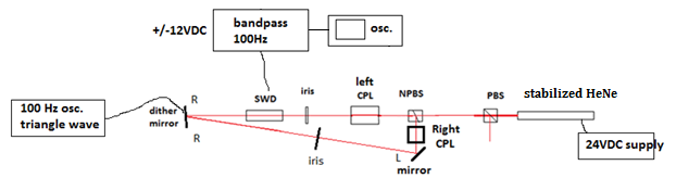
In this second design, the return path through
the
SWD sensor was chosen to follow a different approach, using an
independent arm to the dithered mirror.
This interferometer has one beam stationary
through
the detector, while the return beam oscillates back and forth with
respect to it. This
design did conform to the excel spreadsheet predictions for the
calibration fringe shift due to the laser frequency sweep, and all
points in the path were sensitive to the glass slide test.
Interferometer 3:
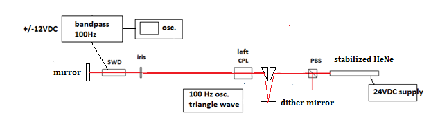
In this third configuration, the dither
mirror was moved to the laser side of the SWD detector. This
configuration causes both beams (forward and return) to move in unison
through the detector when the mirror is dithered. This was done to see
if the result is any different from when only one beam moves. Again,
this interferometer conformed to the predictions of our excel
spreadsheet and was sensitive at all points to the glass slide test.
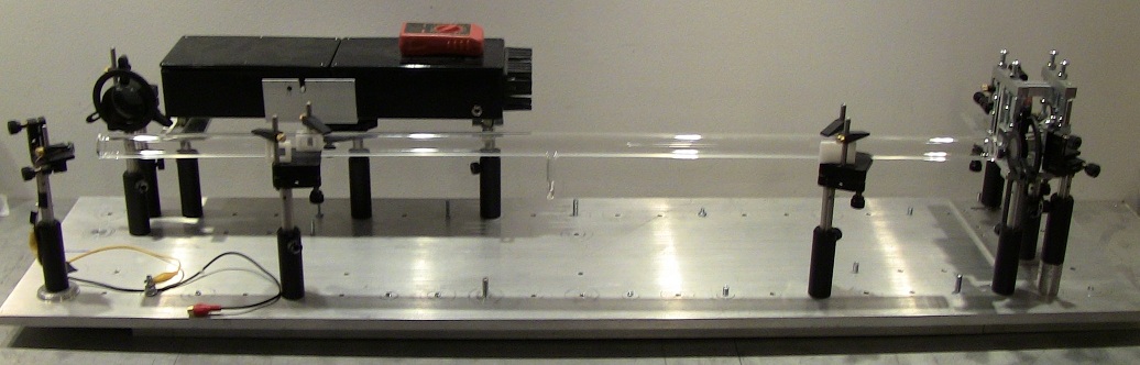
Interferometer 4:
Finally, in this last test, we added a vacuum
path of 91 cm, to determine if the result of experiment 2 and 3 was
affected by the presence of air, since air might be considered a moving
dielectric medium for the light that drags the light at the rotational
speed of the earth. A specially designed vacuum tube evacuated and
sealed at 5X10⁻⁵ Torr was constructed for this purpose.
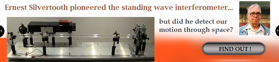
Procedure
The general procedure on start-up was to turn
on the
laser and after a few minutes to count the number of fringe shifts that
occur when the laser intensity sweeps from a minimum on the chosen mode
to a maximum. This was observed using a multi-meter displaying the
intensity of the waste beam polarized components with respect to one
another. After at least ½ hour warm up, the laser would be put into
lock mode. A two channel oscilloscope was used to display the triangle
wave driving the dithered mirror and the SWD output signal (after
amplification and filtering). An example of the two waveforms displayed
on the oscilloscope is shown below:
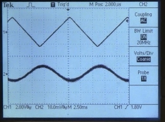
The
intensity of the mirror driving voltage is
always adjusted to the minimum required to display a dither signal of
the same frequency as the triangle wave. Increasing the swing of the
mirror leads to the dither signal becoming an integer multiple of the
triangle wave driving signal, due to the mirror passing through
multiple wavelengths per swing.
It was noted that depending on the optical
adjusts
of the interferometer, it was possible to separate two or more dither
signals of different characteristics – most often there was one signal
generated from the light passing down and back through the planed
optical route, but sometimes another dither signal could be tuned in
that appeared to be due to an internal reflection from one of the
optical faces. In order to distinguish between these spurious signals
and the desired one, it was necessary to put a glass slide between each
of the optical components in sequence after changing an arrangement, to
insure that each optical path segment was sensitive to a change in
refractive index and thus would generate a fringe shift. The optical paths were
then adjusted to maximize this signal and detune any others. The
resulting dither signal was generally incredibly sensitive to
vibrations of any kind, as well as air currents around the apparatus.
Typically a cardboard enclosure was used to prevent air currents from
disturbing the interferometer, particularly during rotation.
Several methods of rotating the optical
breadboard
were tried. The first consisted of a swivel mount bearing mounted under
a wooden slab – this bearing proved to be too noisy, and eventually a
pedestal mount was used with the optical breadboard mounted directly on
top. This was much smoother in rotation. In order to get a somewhat
vibration free rotation of the breadboard through the cardinal
directions, usually a chord was wrapped around the pedestal mounts
sufficiently to generate a tension – the chord was connected to the
platform on which the breadboard rested, and this tension was used to
uniformly pull the device around as the chord unwound. Generally this
procedure was repeated at least 50 times for each arrangement, with the
total swing varying between 45 and 180 degrees. The fringe shift was
noted over the course of each swing, as well as the degrees of the
compass traversed. This data was then tabulated into a radar plot
showing the average fringe shift, covering all 360 degrees.
Photographs of the four interferometer designs
are
shown below, the first two shown on the original swivel mount, while
the second two are shown on the pedestal mount inside of the cardboard
shielding used to block air currents for disrupting the interference
pattern at the SWD.
Interferometer 1:
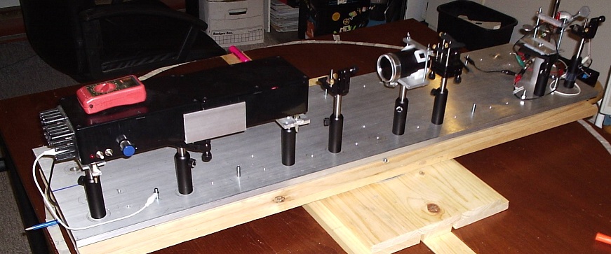
Interferometer 2:
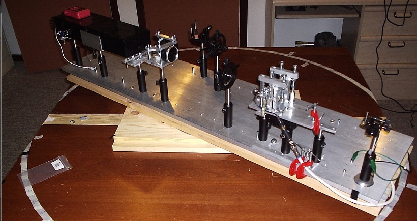
Interferometer 3:
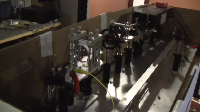
Interferometer 4:
The interferometers were also levelled around
all 360 degrees to reduce the incidence of gravity related stresses on
the optical components.
Predicted
Outcomes
Since these standing wave interferometers
serve as
very sensitive one-way wavelength of light detectors, what kind of
output change would we expect if the one-way speed of light is
different in various cardinal directions? Since C=f l, we would anticipate that the fringe shift
around 360 degrees due to a wavelength change would correspond to the
change in the one way velocity of light in the same directions.
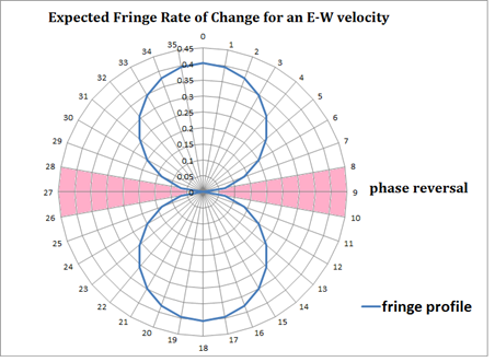
However, this fringe shift would not be linear, since the rate of
change in the fringes with angle should depend on the Sine of the angle
with the direction of the aether drift. In other words, although the
wavelength of light would be shortest when the long axis of the
interferometer is pointing into the oncoming aether drift (and longest
when pointing in the opposite direction), the rate
of change of the wavelength will be greatest when the long
axis sweeps through the perpendicular line to the direction of aether
motion. This is displayed in the diagram below. The blue line
represents the rate of change of the fringe shift for a hypothetical
aether wind coming from the east (9= 90 degrees on the compass). At the
direction where the interferometer long axis crosses over the E or W
line, the fringe shift slows down, halts, and then reverses direction,
following the change in the
detected wavelength.
The diagram above is thus what we would
expect if we were detecting the rotational motion of the interferometer
with respect to a stationary aether fixed to the ECI frame of the
earth. We would also expect such a pattern if the interferometer was
swept through a aether drift due to our motion with respect to the
Cosmic Microwave Background (CMB) except that the phase reversal point
would correspond to the direction towards the constellation Leo and
would vary with direction consistent with the change in the sidereal
space direction with respect to our compass. Also, the fringe shift due
to our motion with respect to the CMB would be at a maximum
approximately 2000x larger than that expected for the rotational
velocity of the earth, if it is detectable. A third possibility is that
the wavelength of light is isotropic with respect to the rotating earth
(i.e. the ECEF frame) at a given latitude, a result which would support
a Stokes aether model, or relativity, or any model of light where the
one-way change in the wavelength of light due to motion is
undetectable.
Experimental
Results:
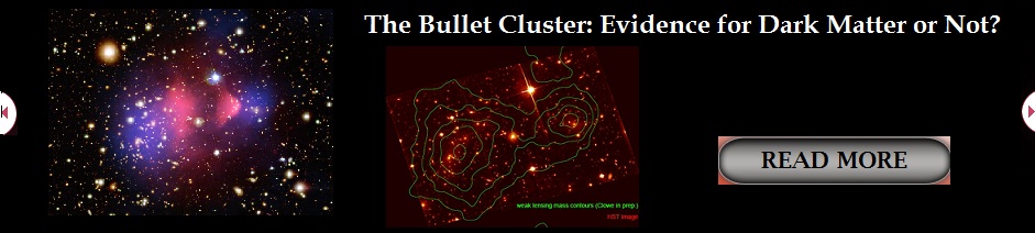
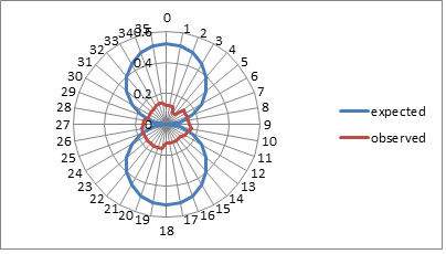
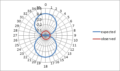
The experimental
results for interferometer 2 are shown below. The low fringe change
around 360 degrees of rotation immediately ruled out any detectable
wavelength change due to our motion with respect to the CMB or our
orbital motion. The
expected rate of change of the fringe pattern for an E-W velocity of
336 m/s is shown below in blue. The expected fringe shift around 360
degrees was 11.9 full fringes. The actual fringe shift was 4.94 (red)
and appeared to be random and due to the vibrational motion of the
interferometer as it turned on its platform. No distinct phase
reversals or rate of change pattern was observed. This suggests that no
aether wind was detected in any direction with a velocity greater than
our noise level of 139 m/s. n
= 25.
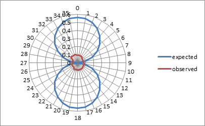
The
experimental results for interferometer 3 are somewhat similar. For 83 determinations, the
average was a uniform fringe shift of 2.79 over 360 degrees, whereas we
expected 9.2 full fringes for a velocity of 336 m/s due to the rotating
earth at our latitude. This puts the maximum velocity possible at less
than our noise level of 102 m/s.
Since the results were considerably smaller
even than would be expected for the rotational velocity of the earth at
336 m/s at our latitude, it was decided to test to see if the
atmosphere of the earth itself might be dragging the light, much like
other dielectric mediums drag light
(fibre optic cable, water, etc.), the
experiment of
Fizeau being a notable example. This might be unlikely, since the
Fresnel drag equation does not suggest there would be substantial drag
for air with a refractive index of very close to 1, but we decided to
rule it out as a possibility nonetheless. Assuming full drag by air,
and no drag by a vacuum, we would expect a fringe shift of 12.88 over
360 degrees of rotation, based on our vacuum path of 91 cm in length.
The results of these tests are shown below, n = 50. The actual fringe
shift was much lower again, at 2.97 fringe shifts, corresponding to a
maximum velocity of not more than 77 m/s.
Discussion
The
experimental results do not conform to our original expectation that an
aether wind generated fringe shift would be visible. We found that the
one way speed of light appears to be isotropic, at least down to our
noise threshold of 77-139 m/s, depending on the arrangement. Further,
with interferometer 3 we did observe at least once a fringe shift of
zero, for each chosen direction of the compass. . The apparent “null”
result however, after careful analysis, can be found to be explained
entirely by the expectations of Lorentz ether theory (LET).
A
frequency shift on the laser would be expected due to its rotational
movement around the platform axis with respect to any hypothetical
aether wind. This is because a moving clock experiences a time dilation
effect – Lorentz ether theory sees this as a clock error caused by the
motion of the clock with respect to a preferred frame for light,
whereas relativity interprets this time dilation as a real change in
the passage of time for the clock. This frequency shift should be equal
and opposite the fringe shift along the optical path using Lorentz
ether theory. This was the criticism put forward by Tyapkin to explain
why the Cialdea experiment, and virtually all one way speed of light
tests cannot generate a fringe shift as might be anticipated. This was also pointed out
by Ruderfer in explaining the lack of a fringe shift in Mossbauer
tests.
The method of Tyapkin, as applied to this
particular experiment, predicts that the laser will experience a time
dilation of:
Dt = t*(1/(1-v2/c2)*(L/2c2)*V*wrot*sin(q)
Resulting in an ultimate counteracting fringe
shift along the optical path of:
Dfringe
= t*(1/(1-v2/c2)*(L/2cl)*V*wrot*sin(q)
Where:
t = rotation time
(s)
wrot
=
angular velocity of the laser
v = aether wind
(m/s), sin(q) = average sine
value over 90 degrees x 2 = -0.636619783
x 2
c = speed of
light (m/s), L
= one way optical path length (m)
The fringe shift
would then be double this amount since in the standing wave
interferometer the fringe shift from the return beam adds to the amount
of the forward beam rather than cancelling. This
equation was put into a simulator of the interferometers used in this
experiment. One example is interferometer 3; the simulator can be found
here. As can be seen from this simulator, the
fringe shift along the optical path due to the rotation of the
interferometer with respect to an aether wind is perfectly cancelled by
the frequency change of the laser due to the time dilation involved in
its motion. This is regardless of the angular velocity of the laser or
its position on the optical table with respect to the axis.
Interestingly, by this same argument, the
relativistic interpretation of this experiment would actually predict a
fringe shift. Using relativity, there would be no fringe shift along
the path since the speed of light would be predicted to be c in all
directions. However, the laser frequency shift caused by the rotational
motion of the interferometer would cause a fringe shift proportional to
v2/2c2, where v is the
tangential velocity of the laser. This should be significant enough to
measure in some high rotational speed experiments.
It should be noted that a similar argument can
be
made to explain the null result of one-way velocity of light
experiments involving two lasers. A spreadsheet simulator of this kind
of experiment is given here. Given the ultimate resolution of this
experiment at around 1 fringe shift over 180 degrees rotation, there is
not sufficient resolution to distinguish between the null result
predicted by Lorentz Ether theory or the very small positive result
predicted by relativity.
Conclusions
In
the original premise of this experiment in was believed that this
interferometer would be successful in detecting an aether drift if a
preferred medium of space exists. However, , as has been explained in
the discussion, this anticipated result turns into a null result when
one takes into account the frequency shift of the laser clock due to
its rotational motion around the table. This frequency shift is called
for in both Lorentz ether theory and relativity, and thus within the
resolving power of this experiment we cannot distinguish between the
predicted result of the two theories. This same frequency shift in the
rotating clock is the reason why other one-way speed of light
experiments with rotating lasers, masers, or using the Mossbauer effect
cannot distinguish between the two theories.
References
[.1.]
A.
A. Tyapkin, Lett. Nuovo Cimento, 7, 15, pp. 760-4, (1973).
[.2.]
H.
Lorentz, Lectures on Theoretical Physics,
V.1 pp. 14-19 (1927).
[ 3 ]
J.
Larmor, Aether
and Matter, Cambridge University Press (1900).
[
4 ] A.
Michelson, E. Morley, Am. J. Sci, 34,
203, pp. 333–345 (1887).
[
5 ] R.
Mansouri, R. Sexl, Gen. Rel. Grav., 8,
10, pp. 809-14 (1977).
[
6 ] C.
Moller, Suppl. Nuovo Cimento, 6,
pp. 381 (1957).
[
7 ] M.
Ruderfer, Phys. Rev. Lett. , 5, 5,
pp.191-2 (1960).
[
8 ] K.
Turner, H. Hill, Bull Am. Phys. Soc., 8,
pp. 28 (1963).
[
9 ] D.
Champeney, et. al., Phys. Lett., 7,4
,pp.241-3 (1963).
[10] E.
Preikschat, The Mossbauer Effect and Tests of
Relativity,
Thesis, U. of Birmingham, 1968, Chapter 4-10.
[11] R. Cialdea, Lettere
Al Nuovo Cimento, 4, 16, pp.821 (1972).
[12] R.
Hatch, Proc. 58th
Ann. Meeting Inst. Nav.
pp. 70-81. (2002).
[13] M.
Ruderfer, Phys. Rev. Lett. , 7, 9,
pp. 361 (1961).
[14]
R. Mansouri, R. Sexl, Gen.
Rel. Grav., 8, 7, pp. 497-513 (1976).
[15] D.
Marett, A Replication of the Cialdea One-Way
Speed of Light
Experiment (2010). http://www.conspiracyoflight.com/Cialdea/Cialdea.html
[16]
E.W.
Silvertooth, Spec. Sci. Tech. Vol.10, No.1, pp.3-7.
|