        Detecting Earth's Rotation Through Space Using a Large Area Sagnac Interferometer Doug Marett (2011) The YouTube video of this experiment
is here The original Michelson Morley experiment sought to measure earth's motion through space using a purely optical means. As is well known, this experiment failed to detect the translational motion of the earth in its orbit around the sun. The issue, as Lorentz pointed out, is that even if a preferred frame for the speed of light exists, the first order Doppler effects due to translation cancel out around any closed path optical system, and the Lorentz contraction cancels any second order effects. However, these effects do not cancel out in rotation, and it is possible to detect earth's rotational motion through space, and in so doing, demonstrate that the speed of light is not equal to C in the frame of the rotating observer. What this means is that for a perfectly stationary optical device in the laboratory frame, one can detect a difference in the speed of light in the clockwise vs. counter-clockwise directions in a fiber optic loop, and the difference corresponds to the net rotation of the loop with respect to some external preferred frame, that frame might alternatively be referred to as 1) the non-rotating gravitational frame of the earth, or 2) what is commonly referred to as the frame of the "fixed stars". Description
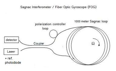
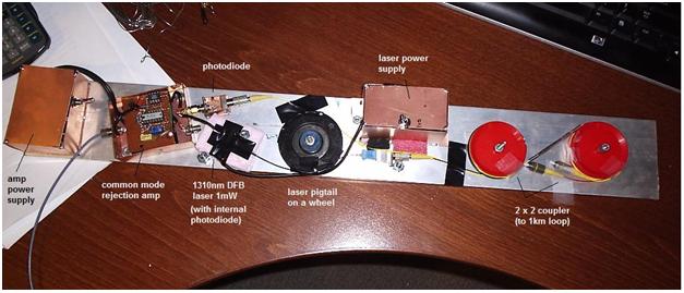
of the Apparatus: The design used herein is a fiber optic gyroscope (FOG) using single mode fiber (SMF-28) rather than the more expensive polarization maintaining fiber. Consequently, the polarization filter is eliminated, but a polarization controller paddle wheel is used to adjust the phase relationship between the clockwise and counter-clockwise propagating beams in the loop. Since we are using SMF-28 fiber, the wavelength of the laser was chosen as 1310 nm, and a 1 mW DFB laser was used with a built-in pigtailed fiber-optic connector. The device also requires a 50:50 2X2 single mode fiber optic coupler. A schematic diagram of the device is shown below:
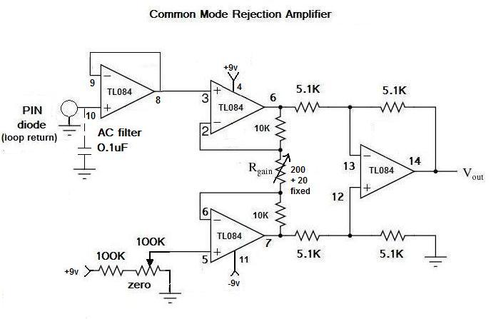
The phase difference between the two beams is then detected at the PIN photodiode detector. A second reference PIN photodiode built in to the DFB laser is used as a comparison voltage source for a common mode rejection amplifier which amplifies the voltage difference detected by 500x to as much as 1150x. Three features are used to achieve the resolution needed: 1) The fiber optic loop is made as long as possible - in our case, we use a loop a full 1 km in length. This gives us 318.5 winds of cable on the loop, enclosing a total area of 250 m2. 2) The radius of the loop is made as large as possible, to maximize the angular velocity of the loop due to earth's rotational motion. In our case the radius is 0.5 meters, giving the loop a circumference of 3.14 meters and a maximum angular velocity of 3.6 E -5 m/s due to earth's rotation. 3) High amplification of the base D.C. signal to make the small velocity differences detectable as a mV difference on an oscilloscope. In order to keep the construction costs low, many of the components were obtained surplus. The laser is available from skyhunt.net, as is the photodiode and the 2X2 coupler. The 1 km fiber optic single mode cable was obtained from Fiber Instrument Sales Inc. Amplifiers and other electronics were built using locally available components. In our first attempt (experiment 1) we used the following common mode rejection amplifier with the voltage gain adjust to 500x and without the reference PIN diode:
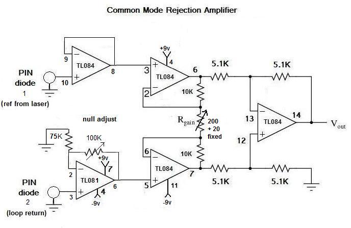
Later, in an effort to reduce RFI noise, and also to compensate for laser intensity drift, a second common mode rejection amplifier was used (experiment 2). This amplifier uses a voltage sample from a photodiode internal to the laser to help compensate for intensity drift. A schematic of this amplifier is shown below:
The output of this amplifier is fed directly to a D.C. voltmeter and/or a digital oscilloscope. The electronics and optical components were mounted on a rigid aluminum plate to insure maximal rigidity of the components. Battery power supplies of 1.2 VDC for the laser and +/- 9VDC for the amplifier were also mounted on the plate. A picture of the completed electro-optic interface (minus the 1 km loop) is shown below:
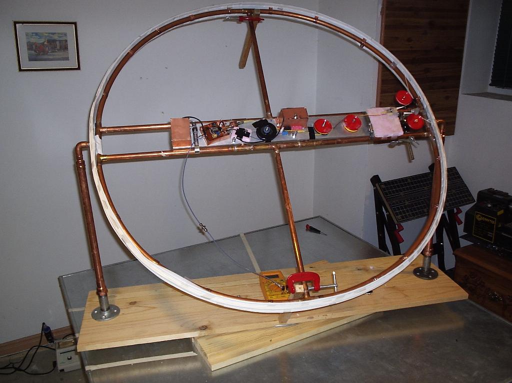
The photodiode/amplifier is currently available from skyhunt.net with a fixed gain of 11x ( the gain can be increased with a small adaptation). Since the purpose of this exercise was to achieve the goal with low cost, readily available components, a 1 meter diameter hoop was constructed from 1/2 inch copper plumbing pipe and fixtures. An aluminum siding metal strip was affixed to this hoop and served as the curved surface for winding the fiber optic cable on. Plastic pulley wheels were used both as structural supports for the fiber optic assembly, as well as for the angling paddles for controlling the phase between the two counter-propagating laser beams. Finally, an equatorial mount was constructed out of wood, with a swivel mount coupled to a metal optical table. This swivel mount allowed the device to rotate 360 degrees horizontally; the greased plumbing connectors on either side of the loop allowed it to also rotate 360 degrees vertically - thus any orientation with respect to sidereal space can be achieved. The completed large area fiber optic gyroscope is shown below.
Determining
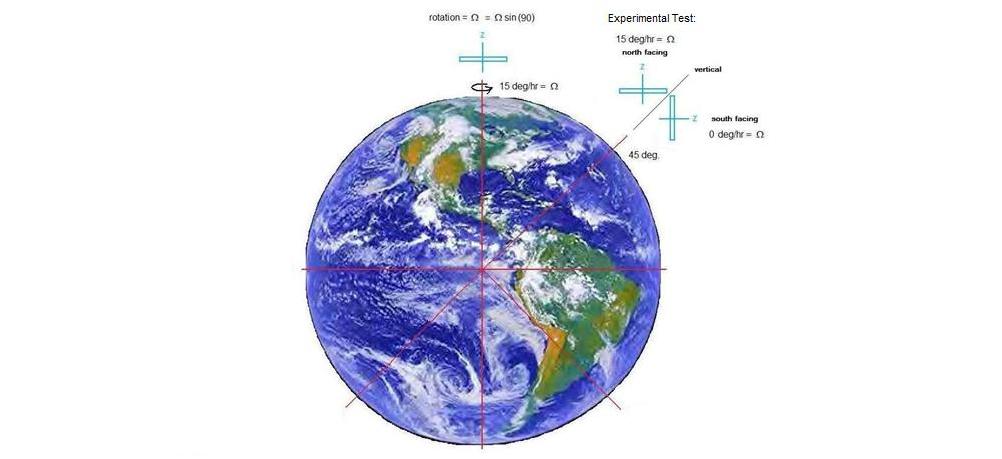
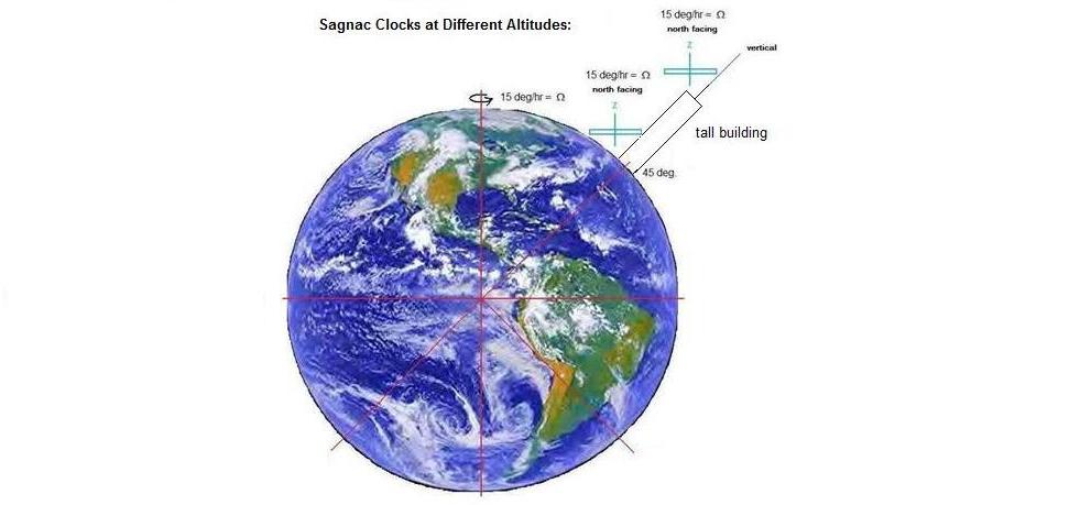
the Best Orientations for Detecting Earth's Diurnal Rotation: If we were performing our experiment at the north pole, then a horizontally oriented Sagnac interferometer would experience a rotation rate of 15 degrees per hour, as shown in the diagram below. Since we are at a latitude of close to 45 degrees (43 degrees, 40 minutes), we have chosen for our experimental test to orient the device with its Z-axis pointing north at an angle of 45 degrees, vs. its z- axis pointing south at an angle of 45 degrees. In the former orientation, the device will experience a near maximal rotation of 15 degrees per hour. However, in the latter orientation, the z-axis will be perpendicular to the north pole, and will thereby experience close to zero rotation due to the earth's motion. For a negative control, we can chose to keep the interferometer at 45 degrees to the horizontal, but point the z -axis either east or west. In these cases, each orientation will experience the same degree of rotation, so the transition from east to west should result in a net change of zero.
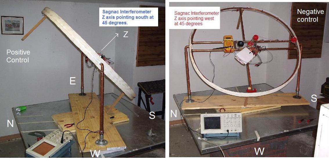
The interferometer orientation is shown above in relation to the earth. The experimental test involves flipping the interferometer from the parallel to perpendicular to the North pole axis orientations, thus showing the maximal change from one orientation to the other. As stated abover, the negative control is the same flipping process, except the transition is along the E-W line instead. Photo's of the actual Sagnac interferometer in various orientations are shown below. The geographic north is marked out with tape on the metal base table. Wood spacers are affixed to the interferometer loop to act as stops when the device is swung from one orientation to another. In the first figure the interferometer is shown in the experimental test orientation with the z-axis pointing south at 45 degrees. In the second figure, the interferometer is shown with its z-axis pointing west at 45 degrees.
Running
the Experiment: 1)
Calibration Before each experimental run, the Sagnac interferometer was calibrated to determine its sensitivity to rotation. This was usually performed by rotating the interferometer horizontally at a fixed speed and determining the mV change per RPM before amplification. Then this value is multiplied by the amplification factor to determine the final sensitivity. Calibrations were for counter-clockwise rotation (same sense as the earth) where the mV change was positive. First
Experiment Calibration (Dec. 15/10): Sensitivity before amplification = 56 mV / RPM After amplification: 56 mV x 500 /(60 x 360) = 1.296 mV for 1 degree/hour Since the earth rotates at 15 degrees per hour, the expected result of earth's rotation = 19.44 mV positive change when the device z-axis is parallel to the north pole vs. perpendicular. Second
Experiment Calibration (Dec. 30/10 after re-build): Sensitivity before amplification = 81.6 mV / RPM After amplification: 81.6mV x 1150 /(60 x 360) = 4.34 mV for 1 degree/hour Since the earth rotates at 15 degrees per hour, the expected result of earth's rotation = 65.2 mV positive change when the device z-axis is parallel to the north pole vs. perpendicular. Experimental
Results: The following table gives the results of the first and second experiment on Dec. 15th and Dec. 30th, 2010. For the experimental test, the interferometer was flipped repeatedly from z-axis north at 45 degrees to z-axis south at 45 degrees. For the negative control, the interferometer was flipped from x-axis east at 45 degrees to z-axis west at 45 degrees. Experimental
Test:
Negative
Control:
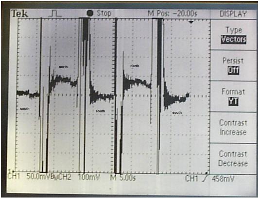
Example: Orientation flipped from south facing to north facing (45 degrees) every 5-10 seconds:
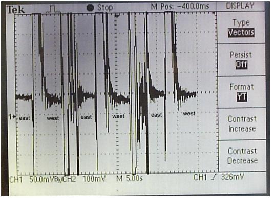
The clear staggering of the traces as the orientation is flipped can be seen. There is considerable noise between each flip due to the vibration of the flip. Example: Orientation flipped from east facing to west facing (45 degrees) every 5-10 seconds:
As can be seen above, the difference between the east and west orientations was close to zero for the negative control. Discussion
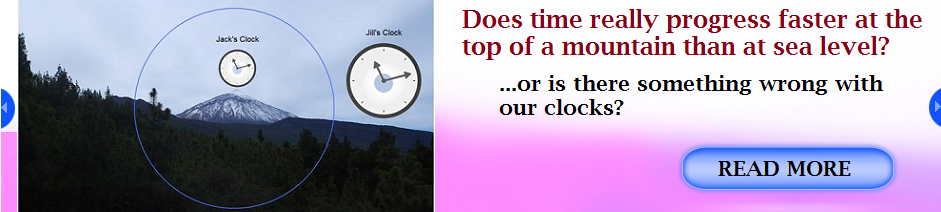
and Conclusions: In this series of experiments we were successful in detecting earth's diurnal rotational motion using a purely optical method. The resolution is quite reasonable considering the low cost design and implementation. The device demonstrates that the speed of light is not constant in the Sagnac interferometer from the perspective of the laboratory observer, even though both the observer and the interferometer are not moving in the laboratory frame. When the device is angled at 45 degrees with the z-axis facing north, the clockwise beam travels faster than the counter-clockwise beam, leading to a phase shift between the two beams at the photodetector. Because the clockwise beam is faster, according to C=fl, the wavelength of the clockwise beam appears longer than the counter-clockwise beam when measured in the laboratory frame. The difference in the velocities of the two beams amounts to the angular velocity of the loop with respect to the pole of the earth (the ECI frame). This is approximately 3.6 E -5 m/s. This amounts to a fringe shift of only 4.2 E -5 between the two beams. However, due to the high amplification used in this system, we are able to detect fringe shifts on the order of 0.7 E -6 of a fringe per mV. With respect to what is the Sagnac interferometer rotating? This experiment reminds us of the dilemma of Newton's bucket. Newton argued that rotation is always with respect to absolute space. Mach argued that rotation is with respect to the full matter content of the universe. Einstein argued instead that rotation is with respect to the local gravitational field - unfortunately for us, these ideas are difficult to discriminate in an experiment performed on the rotating earth, since the fixed stars and the non-rotating gravitational field of the earth represent the same frame. To correctly account for the results of GPS propagation, Lorentz Ether Theory (LET) would also need to accept that gravitational frames are preferred frames for light, but not because of space-time but because a hypothetical medium of space would also be distorted by gravity such that it would affect the speed of light. This means that to distinguish between this updated version of Lorentz theory and the theory of relativity requires proving or disproving instead whether time is absolute (Lorentz) or if it is truly relative to the motion of the observer (Einstein). It is possible using Sagnac interferometers to address the issue of whether time is absolute or relative. Since a Sagnac interferometer can be calibrated to detect earth's rate of rotation (1 revolution per sidereal day, or approximately 15 degrees per hour when aligned parallel to the pole) it can serve as a clock with its period fixed to the sidereal day. If we were to calibrate a Sagnac interferometer at sea level with its z-axis parallel to the pole, and then moved it vertically to 1,000 feet (say in a tall building), the calibration would go off by some small amount (the fringe shift will be slightly less for the same rotation rate). Einstein would argue that time passes more quickly at the top of the building (due to gravitational time dilation), giving the illusion that the speed of light is now faster inside the interferometer. However, from a modernized Lorentzian perspective, the speed of light is argued to be faster at the higher altitude, giving the illusion that time is passing faster, since the clock of the observer counts at a rate dependent on the speed of light in his local environment. Which interpretation is correct? As was discussed in detail in "The Paradox of the Clocks in the Canaries", it boils down to which clock can be trusted - what is measured as the sidereal day at different altitudes, or what is measured on the hands of the clock of the observer. The sidereal day can be interpreted as the better clock - it gives identical readings for the passage of time for all observers at the different altitudes (a set star will pass the zenith of observers at different altitudes simultaneously, minus differences in the propagation delay, which are miniscule). In using the sidereal day period as a standard, the Sagnac clocks become independent of differences in the speed of light at different altitudes. This requires us to re-calibrate our Sagnac interferometer at the higher altitude for its local rate of rotation; we then again can detect the correct length of the sidereal day (the same as at sea level). This means that both the moved Sagnac interferometer before recalibration and the local clock of the observer (say a caesium clock) give the wrong time at higher altitudes, but for a common cause - because the speed of light has changed inside of both in the local environment.
Related
Articles and Videos: 1. Sagnac interferometer Fiber Optic Gyroscope ( FOG ) construction and testing (Video)2. Sagnac
Interferometer / Fiber Optic Gyroscope (FOG) with Improved Resolution
(Video) 3. D.M. Marett (2010) The Paradox of the Clocks in the Canaries 4. D.M. Marett (2010) The Michelson-Gale Experiment 5. Sagnac Interferometer / Fibre-Optic Gyroscope (FOG) Simulator. 6. D.M. Marett (2010) Gravitational Time Dilation - A Lorentzian Interpretation
|